SAM-3 Servo teardown
SAM-3 Servo teardown
![]() by PedroR
by PedroR
Mon Mar 04, 2013 7:29 pm
Hi all
As we get clear of the Christmas aftershock (yay!) we're back to our business of tearing down and hacking the newest products.
We now have the SAM-3 servo (the core of RQ-HUNO) for sale in our store (see here http://robosavvy.com/store/SAM-3 ).
This servo uses the same Daisy Chain technology and exactly the same protocol used by the wCk servos (the ones on the 5710/5720), meaning they can be connected to your 57xx robot.
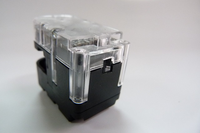
The main advantage of the SAM-3 is its smaller size. It also combines a bit of the black and transparent servos and - as we found - exposes some veyr neat features under the casing.

SAM3_frontback by RoboSavvy, on Flickr

_P1040003 by RoboSavvy, on Flickr
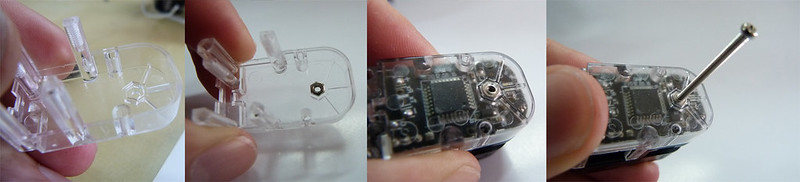
Taking the cover off we see the gearset. Interestingly Robobuilder chose to use 1 metal gear not on the main output shaft but the gear just before that.
This is a 4 gear reduction much like the wCKs.
FYI there's a 5kgf.cm version (SAM-5) with the exact same form factor, just different gear reduction.
Also notice the connector. it's the same used by wCk modules but there's only one on SAM 3 servos (however we have found solder pads for a second one in the pcb on the other side; see bellow).
_P1040013 by RoboSavvy, on Flickr
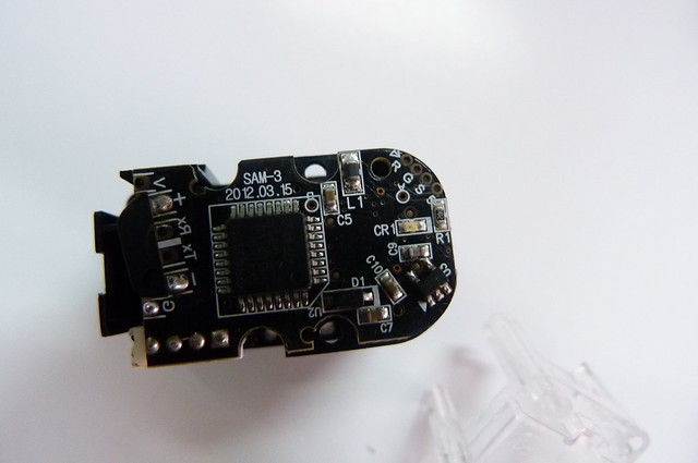
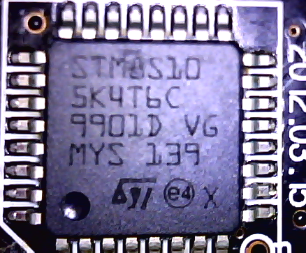
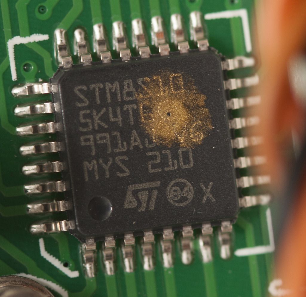
Taking the transparent cover off (on the other side) it reveals a number of unpopulated solder pads and - surprisingly - not an ATMEGA8 processor but an STM processor (SM8S10, still 8 bit):
_SAM-3processor by RoboSavvy, on Flickr
(if anyone has details or would like to clarify what this particular model is, you're most welcome as we couldn't find the datasheet )
Back to the solder pads, we haven't tested all of them but from the silk screen (some) are easy to figure out:
_P1040016 by RoboSavvy, on Flickr
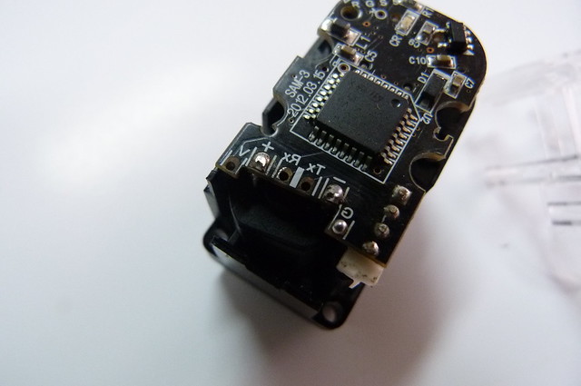
Here we get access to the second connector for the serial port to build the daisy chain.
Since these servos have only 1 external connector there are only 2 ways to build the daisy chain: either build the cable (by connecting multiple RX and TX in parallel or in a W cable as we get in RQ-HUNO) or otherwise use the solder pads here.
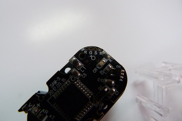
_P1040015 by RoboSavvy, on Flickr
Then there are these mystery solder pads. It's not clear what these are but we suspect they are DIOs for the servo (the wCks also have them). [ again any and all suggestions welcome ]
CR1 is a Blue LED that is included in all SAM-3 servos. It is addressable by using the serial protocol to set the DIO port to 0 or 1. (the original wck protocol gives you access to 2 DIOs and 1 analog in if I'm not mistaken)
I remind you the serial protocol is exactly the same as the one for wCK modules and can be found here (the part that applies to SAM-3 is from page 20 onwards): http://robosavvy.com/RoboSavvyPages/Rob ... manual.pdf
_P1040017 by RoboSavvy, on Flickr
The casing is also carefully thought out with a small hole in the back for cables to exit. The hole is actually very close to the solder points of RX and TX.
SAM3-backhorn by RoboSavvy, on Flickr
One other very neat feature in the casing design is a placeholder for a nut on the opposite side of the horn (for the backhorn). This should make it easier to build systems where you don't want to use the joint system and/or need to attach a proper backhorn.
As far as I recall this was not possible on wCk modules and is a feature on these smaller servos.
The 3 kgf.cm torque is not mind blowing but the rich serial protocol makes this a very appealing servo. The mystery solder pads may well reserve some other interesting features as well.
Also bear in mind the servo can operate in continuous rotation (wheel mode) with built in speed control in addition to position control mode and has a very discrete form factor.
One application I can immediately think of are Pan & Tilt systems for the 5710/5720 robots.
Robobuilder has posted some sample code for interfacing the servo to an Arduino here http://rqhuno.blogspot.pt/search/label/With%20Arduino
If anyone has the motivation to take one and test it to find out what the solder pads do and test the wCk protocol extensively on these servos, email us ( support at robosavvy dot com ) and we'll be happy to give away one servo in exchange for documenting all these hidden features or creative uses in our forum.
Kind Regards
Pedro
As we get clear of the Christmas aftershock (yay!) we're back to our business of tearing down and hacking the newest products.
We now have the SAM-3 servo (the core of RQ-HUNO) for sale in our store (see here http://robosavvy.com/store/SAM-3 ).
This servo uses the same Daisy Chain technology and exactly the same protocol used by the wCk servos (the ones on the 5710/5720), meaning they can be connected to your 57xx robot.
The main advantage of the SAM-3 is its smaller size. It also combines a bit of the black and transparent servos and - as we found - exposes some veyr neat features under the casing.
SAM3_frontback by RoboSavvy, on Flickr
_P1040003 by RoboSavvy, on Flickr
Taking the cover off we see the gearset. Interestingly Robobuilder chose to use 1 metal gear not on the main output shaft but the gear just before that.
This is a 4 gear reduction much like the wCKs.
FYI there's a 5kgf.cm version (SAM-5) with the exact same form factor, just different gear reduction.
Also notice the connector. it's the same used by wCk modules but there's only one on SAM 3 servos (however we have found solder pads for a second one in the pcb on the other side; see bellow).
_P1040013 by RoboSavvy, on Flickr
Taking the transparent cover off (on the other side) it reveals a number of unpopulated solder pads and - surprisingly - not an ATMEGA8 processor but an STM processor (SM8S10, still 8 bit):
_SAM-3processor by RoboSavvy, on Flickr
(if anyone has details or would like to clarify what this particular model is, you're most welcome
Back to the solder pads, we haven't tested all of them but from the silk screen (some) are easy to figure out:
_P1040016 by RoboSavvy, on Flickr
Here we get access to the second connector for the serial port to build the daisy chain.
Since these servos have only 1 external connector there are only 2 ways to build the daisy chain: either build the cable (by connecting multiple RX and TX in parallel or in a W cable as we get in RQ-HUNO) or otherwise use the solder pads here.
_P1040015 by RoboSavvy, on Flickr
Then there are these mystery solder pads. It's not clear what these are but we suspect they are DIOs for the servo (the wCks also have them). [ again any and all suggestions welcome
CR1 is a Blue LED that is included in all SAM-3 servos. It is addressable by using the serial protocol to set the DIO port to 0 or 1. (the original wck protocol gives you access to 2 DIOs and 1 analog in if I'm not mistaken)
I remind you the serial protocol is exactly the same as the one for wCK modules and can be found here (the part that applies to SAM-3 is from page 20 onwards): http://robosavvy.com/RoboSavvyPages/Rob ... manual.pdf
_P1040017 by RoboSavvy, on Flickr
The casing is also carefully thought out with a small hole in the back for cables to exit. The hole is actually very close to the solder points of RX and TX.
SAM3-backhorn by RoboSavvy, on Flickr
One other very neat feature in the casing design is a placeholder for a nut on the opposite side of the horn (for the backhorn). This should make it easier to build systems where you don't want to use the joint system and/or need to attach a proper backhorn.
As far as I recall this was not possible on wCk modules and is a feature on these smaller servos.
The 3 kgf.cm torque is not mind blowing but the rich serial protocol makes this a very appealing servo. The mystery solder pads may well reserve some other interesting features as well.
Also bear in mind the servo can operate in continuous rotation (wheel mode) with built in speed control in addition to position control mode and has a very discrete form factor.
One application I can immediately think of are Pan & Tilt systems for the 5710/5720 robots.
Robobuilder has posted some sample code for interfacing the servo to an Arduino here http://rqhuno.blogspot.pt/search/label/With%20Arduino
If anyone has the motivation to take one and test it to find out what the solder pads do and test the wCk protocol extensively on these servos, email us ( support at robosavvy dot com ) and we'll be happy to give away one servo in exchange for documenting all these hidden features or creative uses in our forum.
Kind Regards
Pedro

Re: SAM-3 Servo teardown
![]() by nicolas gomez
by nicolas gomez
Mon Mar 04, 2013 10:06 pm
[quote="PedroR"]
STM processor (SM8S10, still 8 bit):
_SAM-3processor by RoboSavvy, on Flickr
(if anyone has details or would like to clarify what this particular model is, you're most welcome as we couldn't find the datasheet )
Hiii !
here more info about the microcontroller from the picture the number part STM8S105K4
-Core 16 MHz advanced STM8 core with Harvard architecture and 3-stage pipeline Extended instruction set
-Memories Medium-density Flash/EEPROM: Program memory up to 32 Kbytes Flash; data retention 20 years at 55 °C after 10 kcycles Data memory up to 1Kbytes true data EEPROM; endurance 300 kcycles RAM: Up to 2 Kbytes
-Clock, reset and supply management 2.95 to 5.5 V operating voltage Flexible clock control, 4 master clock sources: Low power crystal resonator oscillator External clock input Internal,user-trimmable 16 MHz RC Internal low power 128 kHz RC Clock security system with clock monitor Power management: Low power modes (wait, active-halt, halt) Switch-off peripheral clocks individually Permanently active,low consumption power-on and power-down reset
-Interrupt management Nested interrupt controller with 32 interrupts Up to 37 external interrupts on 6 vectors
-Timers 2x16-bit general purpose timer, with 2+3 CAPCOM channels (IC, OC or PWM) Advanced control timer: 16-bit, 4 CAPCOM channels, 3 complementary outputs, dead-time insertion and flexible synchronization 8-bit basic timer with 8-bit prescaler Auto wakeup timer Window watchdog, independent watchdog timers
-Communications interfaces UART with clock output for synchronous operation, Smartcard, IrDA, LIN master mode SPI interface up to 8 Mbit/s I2C interface up to 400 Kbit/s
-Analog to digital converter (ADC) 10-bit, ±1 LSB ADC with up to 10 multiplexed channels, scan mode and analog watchdog
-I/OsUp to 38 I/Os on a 48-pin package including 16 high sink outputs Highly robust I/O design, immune against current injection

DATASHEET
http://www.st.com/st-web-ui/static/acti ... 200092.pdf
it is used in FlySky FS-GT3B Digital 3ch 2.4ghz TX & RX LCD Transmitter & Receiver
to speed controler rc
http://www.rccrawler.com/forum/electron ... d-106.html
hope this can help
Regards
STM processor (SM8S10, still 8 bit):
_SAM-3processor by RoboSavvy, on Flickr
(if anyone has details or would like to clarify what this particular model is, you're most welcome
Hiii !
here more info about the microcontroller from the picture the number part STM8S105K4
-Core 16 MHz advanced STM8 core with Harvard architecture and 3-stage pipeline Extended instruction set
-Memories Medium-density Flash/EEPROM: Program memory up to 32 Kbytes Flash; data retention 20 years at 55 °C after 10 kcycles Data memory up to 1Kbytes true data EEPROM; endurance 300 kcycles RAM: Up to 2 Kbytes
-Clock, reset and supply management 2.95 to 5.5 V operating voltage Flexible clock control, 4 master clock sources: Low power crystal resonator oscillator External clock input Internal,user-trimmable 16 MHz RC Internal low power 128 kHz RC Clock security system with clock monitor Power management: Low power modes (wait, active-halt, halt) Switch-off peripheral clocks individually Permanently active,low consumption power-on and power-down reset
-Interrupt management Nested interrupt controller with 32 interrupts Up to 37 external interrupts on 6 vectors
-Timers 2x16-bit general purpose timer, with 2+3 CAPCOM channels (IC, OC or PWM) Advanced control timer: 16-bit, 4 CAPCOM channels, 3 complementary outputs, dead-time insertion and flexible synchronization 8-bit basic timer with 8-bit prescaler Auto wakeup timer Window watchdog, independent watchdog timers
-Communications interfaces UART with clock output for synchronous operation, Smartcard, IrDA, LIN master mode SPI interface up to 8 Mbit/s I2C interface up to 400 Kbit/s
-Analog to digital converter (ADC) 10-bit, ±1 LSB ADC with up to 10 multiplexed channels, scan mode and analog watchdog
-I/OsUp to 38 I/Os on a 48-pin package including 16 high sink outputs Highly robust I/O design, immune against current injection
DATASHEET
http://www.st.com/st-web-ui/static/acti ... 200092.pdf
it is used in FlySky FS-GT3B Digital 3ch 2.4ghz TX & RX LCD Transmitter & Receiver
to speed controler rc
http://www.rccrawler.com/forum/electron ... d-106.html
hope this can help
Regards
![]() by PedroR
by PedroR
Wed Mar 06, 2013 4:26 pm
Hi Nicolas
Thank you for sharing that with us.
I'm still quite curious as to what the "R","G","S" and "5"(?) pins are for.
Anyway I wanted to point out something I believe I missed in my initial port:
the SAM-3 servos come with a Horn that's compatible both with the Rivet system and also with the use of Screws.
Bellow is a picture of the kit contents:

You'll notice the Horn has 4 large holes for rivets and 4 smaller ones where you can fit a nut and use a screw to attach them to other frame systems.
This, combined with the possibility of adding a backhorn (shown in the first post) makes these servos very flexible in terms of use within the Robobuilder system and also outside the Robobuilder ecosystem.
A 4 pin molex to 4 pin molex cable is also included with the servos (this is the same cable that comes in 57xx robots as the connectors are exactly the same).
Regards
Pedro.
Thank you for sharing that with us.
I'm still quite curious as to what the "R","G","S" and "5"(?) pins are for.
Anyway I wanted to point out something I believe I missed in my initial port:
the SAM-3 servos come with a Horn that's compatible both with the Rivet system and also with the use of Screws.
Bellow is a picture of the kit contents:
You'll notice the Horn has 4 large holes for rivets and 4 smaller ones where you can fit a nut and use a screw to attach them to other frame systems.
This, combined with the possibility of adding a backhorn (shown in the first post) makes these servos very flexible in terms of use within the Robobuilder system and also outside the Robobuilder ecosystem.
A 4 pin molex to 4 pin molex cable is also included with the servos (this is the same cable that comes in 57xx robots as the connectors are exactly the same).
Regards
Pedro.
Re: SAM-3 Servo teardown
![]() by Uwe
by Uwe
Fri Mar 02, 2018 3:54 pm
Hello Pedro,
today i found the RoboSavvy Forum and your SAM-3 Servo teardown Post, 5 years to late. But I still answer your question regarding the RGS5:
R stands for Reset and should be connected to Pin1, named NRST
G stands for Ground and should be connected to Pin4, named Vss
S stands for SWIM communication and should be connected to Pin 26, named PD1
5 stands for 5Volt and should be connected to Vdd
The MPU is programmed with this 4 lines via a programming adapter like R-Link i.e.
You should test this statements with a multimeter, as this is only assumption. But I´m not surprised if you can confirm.
Happy to have discovered this piece of internet,
Uwe
