Serial Protocol for Controlling/Playing Motions on KHR3/RCB4
Serial Protocol for Controlling/Playing Motions on KHR3/RCB4
![]() by PedroR
by PedroR
Wed Mar 14, 2012 1:50 pm
Following up to our initial discussions on this thread http://robosavvy.com/forum/viewtopic.php?t=7811, we have put together an English document detailing how to Control Motion Playing through the RCB4 Serial port/serial Protocol.
Our work is actually based on libkondo (by chrivo) and understanding what it does.
Our approach was to document and hard code the Byte sequences necessary for Stopping a motion, Playing a specific Motion number and Querying the motion Status.
While this is a bit of a brute force approach it has worked well for us and reliably for us.
Sequence for Playing a Motion:
To play a Motion there are 4 steps:
- Code: Select all
    Step 1: Send a Command to Stop Current Program and Save Current Status to RAM. It's the same sequence of Bytes all the time regardless of the motion number.

    Step 2: Send the "Run Motion" Command. This command varies depending on the Motion number.

    Step 3: Send Command to restore Current Status. It's the same sequence of Bytes all the time regardless of the motion number.

    Step 4 (OPTIONAL): Wait for the Motion to Complete. You can do it polling the controller every 50ms to obtain Execution Status.
                ""Polling"" the controller for Execution Status is OPTIONAL.
The detailed sequence of Bytes for each Operation as well as Response codes can be found on the Protocol Document we've created.
The part we've documented already offers good flexibility: you can start a motion, stop a motion and a very handy one which is Query Motion status to determine if a Motion is running or not.
Also note that by following the sequence of steps above, it means that if you send another sequence to Play Motion while you're still executing a motion, the Robot will stop the current motion and will initiate the new motion.
Signal Levels and Sending commands Serial without using the Kondo USB Adapter HS:
The Serial Commands are sent to RCB4 through the where the Kondo USb Adapter ICS connects when you want to use HTH.
You should set the Jumper position and connect the cable just as if you were going to use H2H.
It is possible to send commands to RCB4 without using the Kondo USB Adapter HS (ie using your own MCU of a Bluetooth or Zigbee module but please keep reading as there are some odd requirements for talking to the RCB4).
RCB4 uses a Full Duplex bus and the pinout is explained in the picture bellow.
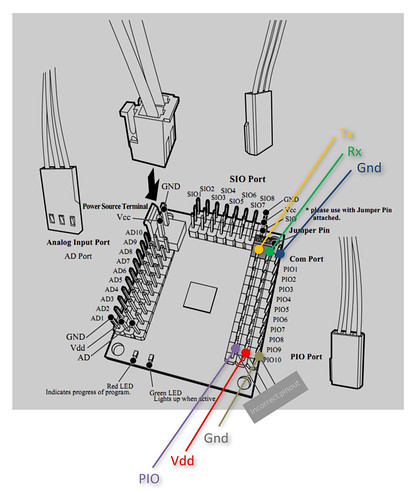
KHR 3HV- RCB4 Controller Pinout by RoboSavvy, on Flickr
In this scenario, you will probably need to a Logic Level converter because RCB4 uses 5V Inverted Logic.
We've built a simple one ourselves to convert from 3.3V TTL to 5V TTL inverted logic which we will hopefully post over the next weeks.
Inverted Logic Essentially means that a 1 is represented by +5V and and idle is represented by a low voltage. This is the opposite of TTL where idle is +3.3V (or +5V) and a "1" is low 0 V.
( It was not completely clear for us if it uses CMOS or TTL logic as the Oscilloscope showed us something but Googling and user reports suggested otherwise but we used TTL levels and it worked fine. )
Also, as a side note, it seems the pinout for the PIO ports is incorrect in the manual. The outer pin is always GND (the manual mentions it's PIO on the outer pin). We _believe_ the pinout shown for PIO is correct in terms of where is Vdd and PIO but we haven't tested it thoroughly.
In terms of communication, another "gotcha" and odd feature of RCB4 is that it uses EVEN parity (instead of the more common "No parity").
Apart from that, you can set Baud Rate of RCB4 to different speed levels (ranging from 1.25 Mbps to 115 200bps) with setting: 8 data bits, 1 stop bit, EVEN parity.
Sample Python test Script
We have also created a simple Python script that you can use to test your code.
To run it you will need install Python and to install the PySerial library.
- Code: Select all
Usage:
        python_playmotion.py "COM_PORT" MOTION_NUMBER [TIMEOUT]

 COM_PORT should be specified in the form of "COMx" for Windows and "/dev/ttySx"
 or equivalent for Linux
This Python code should run on Windows, Linux and Mac.
Finding out more information and more commands:
If you'd like to find out more and really understand the complete structure of the packets (header, command and checksum), you may refer to libkondo and also to the Japanese documentation release by Kondo here http://kondo-robot.com/sys/archives/2477 (thanks to EngineerD for pointing this out)
Downloads:
The full PDF can be found here: http://robosavvy.com/RoboSavvyPages/Sup ... otions.pdf
Python test Script: http://robosavvy.com/RoboSavvyPages/Sup ... ymotion.py
Regards
Pedro.

The byte sequence seems different...
![]() by Ghettokon
by Ghettokon
Sun Apr 29, 2012 8:13 pm
I followed the steps and tried to send the byte sequence based on your document to my KHR-3HV. The robot didn't respond so I did the following: I opened up my H2H, played motion no.1, monitored the byte sequence in the message window. I realized the command byte sequences are different than the ones in the tutorial. The first and the last commands change according to the baud rate too somehow...

![]() by PedroR
by PedroR
Wed May 02, 2012 12:46 pm
We have tested the documentation and script on 3 different HR 3HV Robots and it worked fine on all of them.
Out of curiosity can you let us know what Robot model you have and also the Revision of your RCB 4 HV motherboard?
I don't know how HTH2 affects the firmware onboard the RCB4 as we haven't used it yet.
We tested the docs and protocol on KHR 3HV Robots programmed with HTH v1.x
Thx
Pedro.
![]() by Ghettokon
by Ghettokon
Fri May 04, 2012 3:29 am
I have a black version KHR-3HV (he was my wedding ring barrier!) , and I just updated to HTH4 before the last post. I don't know how to check the revision of my RCB 4 HV motherboard, I bought the set around June 2011 if that helps and the serial no. on the RCB board is Kondo E-139901A.
Motion numbers are exactly the same but the commands are different than yours. I used your commands originally and they didn't work on my robot. Then I open my HTH4 and realized they are different... I think the version difference makes sense.
![]() by Ghettokon
by Ghettokon
Fri May 04, 2012 3:51 am
Play Motions:
http://www.youtube.com/watch?v=tLTJVtg4VNw
Live feed:
http://www.youtube.com/watch?v=anJaYIr3_zg
My ultimate goal is to have it connect to Kinect. The live feed demo above is made possible using this byte command:
0A 00 12 06 05 00 4C 1D 00 90
header ( same for all servo ): 0A 00 12 06
servo no.: 05 (right shoulder)
unknown byte: 00 (never changed in all the servo I worked with)
servo rotation: 4C1D (this is 0 for all servo on trim position)
unknown byte: 00 (never changed in all the servo I worked with)
*evil hex: 90
*This evil hex number increases and decreases with the lower byte of the servo rotation and it skips 1 number for some reason. And this 1 number is different from servo to servo e.g. right shoulder servo skips 44.
I also found out another command which allows you to control all the servos at once. Without documentation, this is really bothersome because I don't know which one is more efficient to use for live feed...
cheers,
Ghettokon
![]() by PedroR
by PedroR
Fri May 04, 2012 2:58 pm
The last byte is most likelly a Checksum.
It should be a result of a Bitwise operation betwen all the bytes that are sent before.
My recommendation to find out how to calculate the checksum is to download libkondo and look in the source code how they're calculating the number.
This is where we based our work to document the bytes sequences to play motions.
Libkondo comes with much more features, including the individual control of the servos (which I believe is what you're trying to achieve).
It's all nicely coded in C and comes with makefiles and everything so it's only a matter of playing with it
Regards
Pedro.
![]() by EngineerD
by EngineerD
Tue May 22, 2012 5:13 pm
not really mistakes, but it's impossible to use just as written.
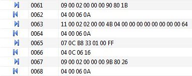
You write that first of all we need to save status to ram - this is not true, by executing 13 00 02 00 00 00 [b]21 87 fd 03 00 00 00 00 00 00 00 00 bd[/b]
you write to ram literal data 21 87 fd 03 00 00 00 00 00 00 00 00 from the start address 00 00 00 .
This data are - 21 87 - value in SystemRegister and it means that [2x10000110000111] from left to right
bit 0 - true means enable ICS Servos(could operate)
bit 1 - true means enable execution programm from ROM
bit 2 - means status of interpolation operation
bit 3 - true means enable vector jumping
bit 4,5 - means ICS frame size (00 - 10ms 01 - 15ms 10 - 20ms 11-25ms )
bit 6,7 - means COM baudrate (00,11 - 115.2kbps 01 -625kbps 10 - 1.25Mbps)
bit 8 - Zero flag
bit 9 -Carry flag
bit 10 - Error flag
bit 11,12 - not used
bit 13,14- means ICS baudrate(00,11 - 115.2kbps 01 -625kbps 10 - 1.25Mbps)
bit 15 - green LED activation
FD 03 00 - address 00 03 FD writes into Program counter (this is main program loop address at ROM according documentation, but in my case it's 00 04 4B, in case of Ghettokon too.)
That's why, if user has different baudrates for ICS or COM, or different frame size it will not work correctly.
Now, i will describe this
first command put robot in wait status(writes value 9080 to system register)
second command put address of wait loop 00044B to command counter and writes 0 to other counters and flags
third command calls motion from address 0133B8 (writes this value to command counter)
forth command switch robot to execution mode(writes 9B 80 to system register) and after this robot start playing motion.
In PedroR manual first and second commands collaborates into one command.

HeartToHeart 4 1.x vs 2.x EEPROM Addressing Changes
![]() by kandrea
by kandrea
Mon Jul 16, 2012 6:14 pm
These are the most significant changes which we noted that promulgated themselves on the RCB-4HV when migrating to HeartToHeart 4 v2.x
MainLoopCmd Address moved from 0x0003FD to 0x00044B
Motion Slot Size changed from 4864 bytes to 2048 bytes
Highest Motion Slot changed from 0x3AEB8 to 0x3C3B8
This is why half of the community is seeing 0x03FD and the other half is seeing 0x044B for the main program loop address.
The 1.X EEPROM mapping is included in a PDF in this archive: http://kondo-robot.com/sys/wp-content/u ... 100807.zip
The 2.X EEPROM mapping is included in a PDF in this archive: http://kondo-robot.com/sys/wp-content/u ... 120420.zip
This was a pseudo-hidden firmware update that HeartToHeart 4 2.1 did in order to expand the available motion slots up to 120 and to make room for some of the other new motion features.
The strings provided by the RCB-4HV Command Generators will produce the proper strings, as listed in the thread. It is just important to use version that generates strings for the software used to flash the ROM.
Hope this helps,
kandrea