Virtual COM port networked to remote Arduino via Linux/WiFi
Virtual COM port networked to remote Arduino via Linux/WiFi
![]() by marco
by marco
Mon Nov 07, 2011 12:21 pm
I’m trying to build a setup in which I can remotely control a Dagu Wild Thumper robot from a windows PC. Besides remote control, I’d also like to have remote uploading capabilities as well as have a webcam onboard the robot, get the video stream to my laptop, process it and send control commands back to the robot, therefore having some kind of closed loop control.
So here you can see a high-level diagram of the desired system:
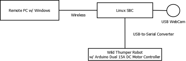
First of all I’ll concentrate on solving the PC-Linux-Arduino communication problem.
Communication with the Arduino is done via USB with a FTDI USB-to-Serial Converter. For this test I used an eBox 3310MX-H Mini PC on which I installed ubuntu from a USB stick and followed the standard installation instructions. I managed to get the system up and running without much hassle. After connecting a USB cable from the eBox to the Arduino I got a nice /dev/ttyUSB0 device to play with. I also connected an ethernet cable from the eBox to my laptop and shared my wireless internet connection, so now I had internet on the eBox and both machines were able to speak to each other.
Next, I needed some software solution that would:
1) On the Linux side, connect to the /dev/ttyUSB0 device on the eBox and relay all incoming/outgoing data to a network port;
2) On the windows side, connect to the network port and create a virtual (fake) COM port that would be fed with data from the network port so that it would act just as if the Arduino board was connected locally.
After some googling I found a nice Wikipedia page that summed up my options for both of these problems: http://en.wikipedia.org/wiki/COM_port_redirector
My first options were socat + HW VSP3.
On the linux side socat behaved very well, it was just a matter of understanding the command line syntax. I ended up with this command:
- Code: Select all
socat OPEN:/dev/ttyUSB0,b115200,crtscts=0 TCP-LISTEN:5000
And now I have socat waiting for someone to connect via TCP to port 5000 and it will handle transferring the data between both interfaces. Cool!
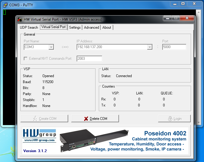
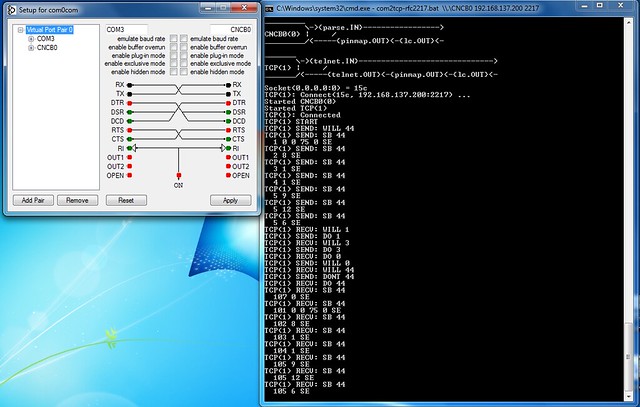
Now for the windows part. I downloaded and installed HW VSP3 and configuration was trivial. I just selected a name for the virtual com port (COM3) punched in the IP address of the eBox and the port number and pressed “Create COM”. Then I opened up Putty, connected it to COM3 and started writing random characters. I could see that for every key press I made the Arduino board’s RX led would blink, so my connection was active.
In order to test the communication I wrote a simple Arduino sketch that would read a byte from the serial port, increment it by 1 and send it back:
- Code: Select all
void setup()
{
  Serial.begin(115200);
}

void loop()
{
  if(Serial.available() > 0)
  {
    int a = Serial.read();
    Serial.write(++a);
  }
}
By now I attempted to upload the program via the virtual com port. It should work, in theory. But it didn’t. Anyhow, everything seemed to be correctly configured so I connected the Arduinto directly to the laptop, uploaded the program, setup the virtual com ports again, opened Putty again and wrote “Hello World!” and this is what I got back:
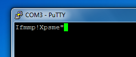
I got exactly what I expected! Hurray, communication does work. But this setup was not good enough for remotely uploading stuff to the Arduino.
It happens that in order to program the Arduino a specific serial port configuration must be used. Trying to upload with verbose output shows us exactly what is happening:
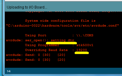
First of all the DTR line is set. This is used to reboot the Arduino so that the boot loader is back in charge of what is happening. Besides that, the baud rate is set to 19200. Since our serial port configuration on the serial side is set beforehand, we need a different solution in order to make changes whenever needed, without having to configure it manually. Luckily, there is already a standard for this, the RFC 2217 called “Telnet Com Port Control Option”. This protocol defines how to send serial port configuration commands through the same stream of data that flows between a virtual serial port and a real serial port.
Unfortunately, the chosen software solution does not implement RFC2217, so we need a different setup.
For the Linux side there seemed to be no ready-to-use solution, so I started thinking about writing my own software. A natural solution would be to write it in Python so that I’d also have a solution that would be cross-platform. Not being familiar with accessing serial ports under Python I came to find the pySerial library and then these guys just made my day: they had an example that implemented exactly what I wanted to implement. It’s called “Single-port TCP/IP - serial bridge (RFC 2217)” and can be downloaded from here
In order to have this up and running, all you need to do is to open a command-line on the folder where you put this script and enter:
- Code: Select all
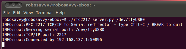
./rfc2217_server.py /dev/ttyUSB0
Now we have a server program that is connected to our USB serial port and has a TCP port listening for incoming connections. Notice that this time we haven’t set any kind of serial port configurations, they will all be set automatically from information received from the controlling program on the windows machine.
Going back to the possible software list, I found out that the com0com+hub4com solution for the windows side supports the RFC 2217. This solution has quite a peculiar way of being setup. Com0com always creates two local virtual ports that are connected to each other. Whatever is sent to one of the virtual ports gets received on the other and vice-versa. In order to connect to a virtual port in another computer you have to use hub4com, which is a command line program. So in order to get this working, you have to do the following:
1. Install com0com. Make sure you get the latest versions. ( download from here )
2. Run the com0com setup program and create a new virtual pair.
3. Add a new virtual pair and change the name of the first port to COM3 (or whichever number you prefer) and press “Apply”. You need to change the name because the Arduino program doesn’t recognise com ports that have strange names.
4. Download hub4com and uncompress the zip file ( download from here )
5. Open up the command line and go to hub4com’s folder.
6. Enter this command:
- Code: Select all
com2tcp-rfc2217.bat \\.\CNCB0 192.168.137.200 2217
You should be looking at something like this:
And on the Linux side:
And voilá! Everything is setup and now you can use the remote serial port as if it was a local port. Normal communication as well as uploading sketches is supported and as long as you have a good network connection you shouldn’t have any problems.
Next step in this project is to have an Omnima - MiniEMBWiFi board onboard the robot running Linux so that our robot can go wireless.
Regards,
Marco Barbosa

![]() by marco
by marco
Fri Nov 11, 2011 1:52 pm
so after getting the serial port forwarding working on the eBox, I went after having this working on the Omnima MiniEMBWiFi board. I got the board and flashed it with the latest official image but I soon found out that there was some kind of problem with the i2c kernel module which prevented video4linux from working.
So I built my own image based on OpenWRT. On the omnima forums I found here instructions to build OpenWrt specifically for this platform. These include a patch to OpenWrt that make it support the Omnima board. I used the patch with the latest trunk head revision. After selecting the target system I chose the software I wanted to have on the new image. For me that was:
- kmod-usb-serial
kmod-usb-serial-ftdi
kmod-usb-serial-pl2303
kmod-usb-video
kmod-video-core
kmod-video-uvc
python
Then I entered “make” and just waited a bit for all the code crunching to finish. Unfortunately, I ended up with this error:
[mkwrgimg] *** error: stat failed on /home/gato/openwrt_sandbox/trunk/bin/ramips/openwrt-ramips-rt305x-dir-300-b1-squashfs-sysupgrade.bin, No such file or directory
After googling a while, I discovered here that it was a very simple solution: I was including too much stuff in the image and it was too big to fit the flash. The error message could be more specific though. Deselected python and all went well. Flashed the card, booted and everything was up and running.
I connected the USB camera and the Arduino board through a USB hub and got the devices I expected: /dev/video0 and /dev/ttyUSB0
I installed python and mjpg_streamer via the LuCI interface and started the mjpg_streamer, I was able to get 30fps with a 160x120 resolution, but lowered it to 20fps. I believe it will be more than enough for controlling the robot. The command was:
- Code: Select all
mjpg_streamer -i "input_uvc.so -y -d /dev/video0 --resolution 160x120 --fps 20" -o "output_http.so -w /webcam_www"
Next I installed pySerial and got all the virtual com ports setup done as in the previous post.
Now comes the strange part.
I was looking at the video stream via mjpg_streamer’s stream webpage and framerate was high as expected. But once I started the rfc 2217 server, the framerate dropped dramatically and there started to be a huge latency on the video. As soon as I killed the rfc 2217 server, the framerate would come back to normal.
My first suspicion was that this could be due to too much CPU usage by the rfc 2217 server, but in fact that was not the case:
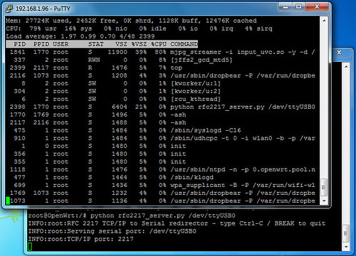
Somehow, mjpg_streamer jumped to 80% cpu usage while before starting the rfc 2217 server it was around 40%. And the rfc 2217 server was just sitting still, not writing anything on the serial port nor having any outside TCP connection.
In order to further understand what was going on, I built scripts that wrote something to the serial port once a second:
using python and pyserial
- Code: Select all
import serial
import time

ser = serial.Serial('/dev/ttyUSB0')
ser.timeout = 1
ser.writeTimeout = 1
print ser.getSettingsDict()
while True:
        ser.write("hello")
        print "wrote to serial..."
        time.sleep(1)
plain python using /dev/ttyUSB0 as a file
- Code: Select all
import time

f = open('/dev/ttyUSB0', 'w')
while True:
        f.write('Hello World!')
        f.flush()
        print 'wrote stuff...'
        time.sleep(1)
shell script
- Code: Select all
root@OpenWrt:/# cat print.sh
#!/bin/ash
while(true) do echo "Hello World!" ; sleep 1 ; done
which I started as
- Code: Select all
./print.sh > /dev/ttyUSB0
The behavior was the same on all three, but then I rebooted and experimented again. Both the shell script and the plain python solution started behaving differently. They would slow down the camera for a while, but then the system seemed to recover and camera framerate went back to normal. But when I used the pyserial-based script, the camera slowed down and stayed that way until I killed the pyserial program. And after this, the other scripts would exhibit the same behavior. Rebooting would bring everything back working for the plain python and shell script again.
So I started to suspect that some kind of state/configuration was being maintained by the serial port. I installed stty in order to inspect what were the configuration of the port.
On reboot, all I get is this:
- Code: Select all
speed 9600 baud; line = 0;
-brkint -imaxbel
And this stays the same after running the plain python and shell scripts. But after running the pySerial-based script, the configurations change to this:
- Code: Select all
speed 9600 baud; line = 0;
min = 0; time = 0;
-icrnl
-opost
-isig -icanon -iexten -echo -echoe -echok -echoctl -echoke
If I enter the command
- Code: Select all
stty -F /dev/ttyUSB0 sane
I get this simple configuration:
- Code: Select all
speed 9600 baud; line = 0;
and everything starts working again. The funny thing is if I do this command while the rfc 2217 server is working the camera gets ok after a while. So I can only conclude that this has something to do with one particular setting that makes the ftdi driver do something with the USB bus that interferes with the camera.
I’m a bit lost right now, do any of you have any kind of pointers for me? What should I test? There doesn’t seem to be any problem with the configuration of the port or with any of thos options. I tested the same setup on a laptop and it worked fine.
I guess that if I can’t get this solved I’d have to use the boards serial port and lose the serial console. I’ll just have to be sure to have a working network configuration at all times in order to not get locked out.
Cheers,
Marco
![]() by marco
by marco
Mon Nov 14, 2011 10:59 am
I'm using the physical serial port now. Disabled the the console on the serial port as described here and used a logic level converter between the Omnima board and the Arduino since one uses a 3.3V level and the other 5V.
Now I'm able to stream video and have a virtual serial connection to the robot. On the downside, in order to remotely upload code to the Arduino, now the reset button has to be pressed manually as neither the Omnima board has a DTR out pin, nor the Arduino exposes any input for this signal.
Cheers,
Marco
![]() by PedroR
by PedroR
Tue Nov 15, 2011 6:59 pm
Marco has been making steady progress on this kit and we're now at a point where we're able to put it up for pre Order here http://robosavvy.com/store/product_info ... ts_id/1928
(there's also a nice video of it working, on the product page)
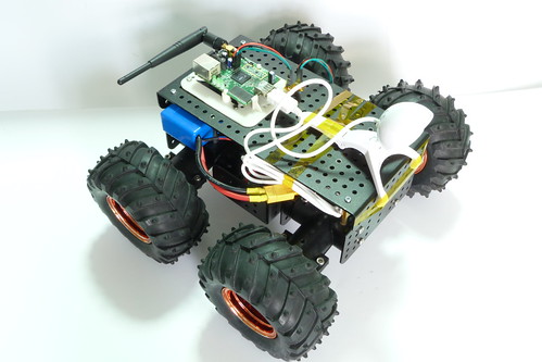
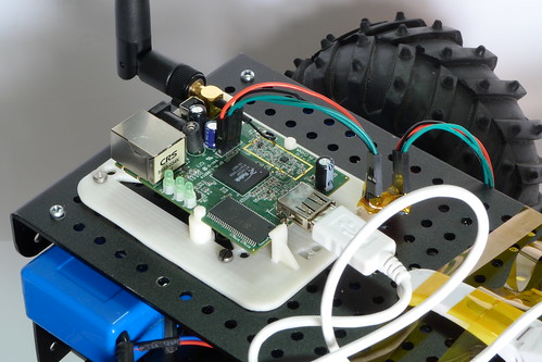
The first Pack that will be "linuxified" is the Wild Thumper 4WD.
Here are some preliminary pictures of the kit:
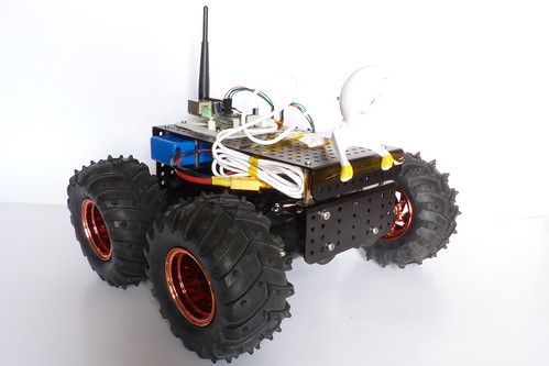
Linuxified Wild Thumper 4WD by RoboSavvy, on Flickr
Linuxified Wild Thumper 4WD by RoboSavvy, on Flickr
Linuxified Wild Thumper 4WD by RoboSavvy, on Flickr
For this project we're using the Omnima Board with a UVC webcam (not sure if this will be the one in the final version).
The console has been detached from the Serial port and the Arduino (Wild Thumper) has been connected to the Serial port via a Logic Level converter (the MiniEMBWiFi is 3.3V TTL where the Wild Thumper is TTL 5V).
The way the complete system works is this:
- The MiniEMBWiFi relays images back tot he PC via WIFi
- Images are processe don the PC (we're using Roborealm for it's ease of use although users may add others).
- The result of the processing is relayed back tot he robot via the Virtual COMM port (See the first post).
The commands sent are essentially commands to move the Wild Thumper, using a simple protocol written/recognized by an Arduino Sketch.
BTW the white support for the MiniEMBWiFi was desgined and printed here at RoboSavvy with our Thing o Matic
Marco should be following up on this in the next days.
Pedro.

![]() by marco
by marco
Wed Nov 16, 2011 10:06 am
as Pedro said, I just finished doing a first complete test with the whole system and with video processing and control being done in Roborealm.
Getting video from the robot into Roborealm was pretty straight-forward. Roborealm has a “Read HTTP” module that does the trick. In my case, I just had to set the URL to
- Code: Select all
http://192.168.1.96:8080/?action=snapshot
Set refresh rate to “ASAP” press start and image input was done.
Next I set up a simple filtering pipeline for a red colored ball. Added a mean filter with a window size of 5 just to smooth the image, and added a “RGB_Filter” and configured it as you can see in the image:
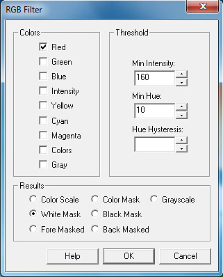
rgbfilter by RoboSavvy, on Flickr
Next in the pipeline is a “Center of Gravity” module. Image of how I set it up follows:
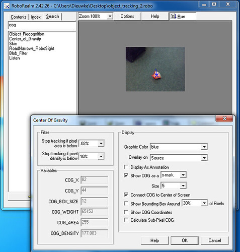
cog by RoboSavvy, on Flickr
The “Center of Gravity” module will track the center of the detected red pixels.
Now we need to transform this information into something useful for motor control. In order to control the robot, we need a protocol defined for the data that is sent to the Arduino controller. The Dagu Wild Thumper robot has an official source code that supports serial communication and has a protocol defined. In order to control the motors, essentially one has to send a 6 byte string formatted as following: “HB[left motor mode][left motor speed][right motor mode][right motor speed]”. The motor mode has 3 possible values:
0: move the wheels backwards
1: stop the wheels
2: move the wheels forwards
The speed value ranges from 0 to 255.
In order to calculate these values I added a Visual Basic Script. The code for it is:
- Code: Select all
midx = GetVariable("IMAGE_WIDTH") / 2
midy = GetVariable("IMAGE_HEIGHT") / 2
cogX = GetVariable("COG_X")
cogY = GetVariable("COG_Y")
cogArea = GetVariable("COG_AREA")

offset = (cogX - midx) 'offset from center in pixels

left_motor = offset * 175 / midx 'multiply by magic constant
right_motor = -left_motor

If(cogArea < 75) Then
   left_motor = 0
   right_motor = 0
End If

If(left_motor < 0) Then
   left_mode = 0
   left_motor = - left_motor
Else
   left_mode = 2
End If

If(right_motor < 0) Then
   right_mode = 0
   right_motor = - right_motor
Else
   right_mode = 2
End If

SetVariable "LEFT_SPEED", CInt(left_motor)
SetVariable "RIGHT_SPEED", Cint(right_motor)
SetVariable "LEFT_MODE", CInt(left_mode)
SetVariable "RIGHT_MODE", Cint(right_mode)
And finally, we need a module to send what we just calculated in VB. Roborealm has a module named “Serial” for general purpose Serial communication.
In order to make it send variable values in simple binary instead of coding it into ASCII, they just need to be preceded by a backslash in the message definition. So the setup for this protocol is the one you can see in the image:
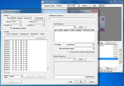
serial by RoboSavvy, on Flickr
And that’s pretty much it. The video shows the first test of this setup and it shows the behavior that I was expecting. More fine tuning will eventually make this much more stable, but it surely shows the potential that this kind of setup has.
Cheers!
Marco
ARDUINO CODE
![]() by matterest
by matterest
Wed May 30, 2012 2:56 am

![]() by PedroR
by PedroR
Wed May 30, 2012 10:05 am
When building and loading code into the Wild Thumper make sure to open the .h file and set the option to enable "Serial Communication". It's a constant there that is commented in code.
We then simply relay Serial Commands to pins 0/1 of the Arduino (the Arduino UART) to command the Robot movement.
Pedro.
arduino code
![]() by matterest
by matterest
Wed May 30, 2012 6:43 pm
![]() by PedroR
by PedroR
Wed May 30, 2012 6:47 pm
At first glance I would be inclined to believe it's either something that changed in the latest Arduino versions or otherwise some difference between the original Wild Thumper board and yours (in case you're using some other board).
Regards
Pedro