DAGU Racer 01 Bluetooth Car teardown and review
DAGU Racer 01 Bluetooth Car teardown and review
![]() by PedroR
by PedroR
Mon Apr 02, 2012 5:09 pm
hi all
We've now got the a new "RC car" in our catalog from DAGU: the Racer 01.
This is a Bluetooth Controlled Car that comes with an Android App to remote control it from your Android phone.
(Android Remote Controlled robots/gadgets seem to be getting trendy!)
One neat thing about the car is the PCB and its hacking potential.
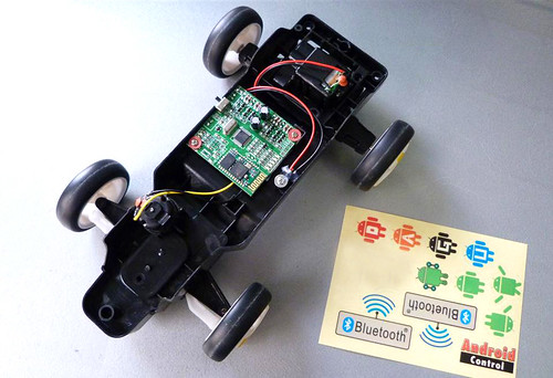
Racer 01 Overview by RoboSavvy, on Flickr
The PCB features an ATMEGA48U, a Bluetooth module running with SPP Profile, LiPo battery charging circuit and additionally controls 2 DC motors.
If you're into hacking this is a perfect board to automate exiting equipment that requires simple actuators.
Here's is the teardown:
The PCB:
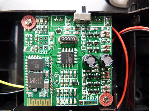
Racer 01 Main Board w/ Bluetooth Chip (SPP) by RoboSavvy, on Flickr
The key chips are:
- Processor: ATMEGA48U
This processor does not have any bootloader but may be reflashed using the exposed ISP header.
- Bluetooth Chip: "CSR BlueCore BC417143B"
This is operating under the Serial port profile.
This suggests that the Serial protocol can be reverse engineered and a Control App can be written easily on any Bluetooth enabled device (such as a PC).
We haven't yet had a chance to check out the protocol but there are 2 solder pads on the board (R and T) that suggest they are RX and TX (where you can spy data flow)
The datasheet for this module is available here http://www.ic-on-line.cn/view_download. ... &file=0271\bc417143b-es-irn_349928.pdf
(if the link is no longer valid, try googling for "BC417 datasheet")
In addition the board includes a simple Circuit to Charge the LiPo and can Drive 2 small DC Motors directly.
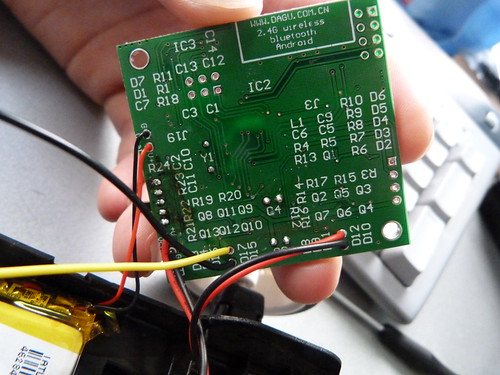
Bottom of the Racer 01 Control Board by RoboSavvy, on Flickr
The back of the board is quite simple.
You can see everything is soldered directly on the board: the LiPo, 2 DC motors (one for Forward/Reverse and the other one for steering Left/Right)
The LiPo and power connector are also directly soldered (the Power connector is located under the chassis; a cable is included to connect it to a USB port for charging).
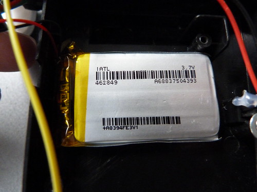
Racer 01 LiPo Battery pack by RoboSavvy, on Flickr
The battery is a simple 1 cell LiPo (3.7V).
There's nothing special about it except a small circuit inside it. I'm not sure if this one of the those standard circuits to protect the LiPo from excess current draw and general damage or if it serves any other purpose.
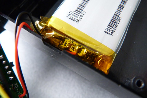
LiPo Circuit by RoboSavvy, on Flickr
The capacity of the LiPo wasn't indicated on the package but from its size I would say it's somewhere between 800mAh and 1000mAh.
We hope you get excited about the product (especially the potential of the board itself) and we hope to post some additional information including the Serial protocol very soon.
Regards
Pedro.
We've now got the a new "RC car" in our catalog from DAGU: the Racer 01.
This is a Bluetooth Controlled Car that comes with an Android App to remote control it from your Android phone.
(Android Remote Controlled robots/gadgets seem to be getting trendy!)
One neat thing about the car is the PCB and its hacking potential.
Racer 01 Overview by RoboSavvy, on Flickr
The PCB features an ATMEGA48U, a Bluetooth module running with SPP Profile, LiPo battery charging circuit and additionally controls 2 DC motors.
If you're into hacking this is a perfect board to automate exiting equipment that requires simple actuators.
Here's is the teardown:
The PCB:
Racer 01 Main Board w/ Bluetooth Chip (SPP) by RoboSavvy, on Flickr
The key chips are:
- Processor: ATMEGA48U
This processor does not have any bootloader but may be reflashed using the exposed ISP header.
- Bluetooth Chip: "CSR BlueCore BC417143B"
This is operating under the Serial port profile.
This suggests that the Serial protocol can be reverse engineered and a Control App can be written easily on any Bluetooth enabled device (such as a PC).
We haven't yet had a chance to check out the protocol but there are 2 solder pads on the board (R and T) that suggest they are RX and TX (where you can spy data flow)
The datasheet for this module is available here http://www.ic-on-line.cn/view_download. ... &file=0271\bc417143b-es-irn_349928.pdf
(if the link is no longer valid, try googling for "BC417 datasheet")
In addition the board includes a simple Circuit to Charge the LiPo and can Drive 2 small DC Motors directly.
Bottom of the Racer 01 Control Board by RoboSavvy, on Flickr
The back of the board is quite simple.
You can see everything is soldered directly on the board: the LiPo, 2 DC motors (one for Forward/Reverse and the other one for steering Left/Right)
The LiPo and power connector are also directly soldered (the Power connector is located under the chassis; a cable is included to connect it to a USB port for charging).
Racer 01 LiPo Battery pack by RoboSavvy, on Flickr
The battery is a simple 1 cell LiPo (3.7V).
There's nothing special about it except a small circuit inside it. I'm not sure if this one of the those standard circuits to protect the LiPo from excess current draw and general damage or if it serves any other purpose.
LiPo Circuit by RoboSavvy, on Flickr
The capacity of the LiPo wasn't indicated on the package but from its size I would say it's somewhere between 800mAh and 1000mAh.
We hope you get excited about the product (especially the potential of the board itself) and we hope to post some additional information including the Serial protocol very soon.
Regards
Pedro.
