Wild Thumper speed control with encoders
Wild Thumper speed control with encoders
![]() by MarcoP
by MarcoP
Fri Jun 29, 2012 3:59 pm
The main limitation we have had regarding the Wild Thumper was the ability to do speed control, due to the lack of encoders.
So we have taken care of that:
We got encoders for the wheels.
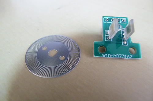
This encoder consists of a stainless steel disk with 60 slots, that rotates between an infra-red emitter and receiver. This gives us a digital signal that changes 60 times per wheel rotation.
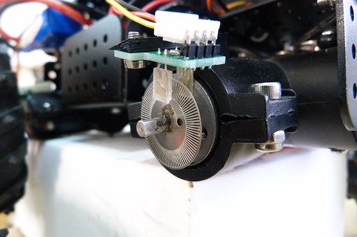
The disk goes onto the shaft and the wheel goes on top.
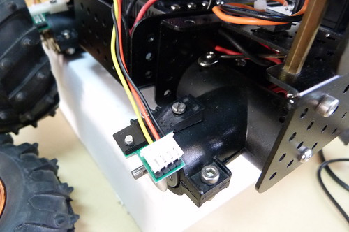
We designed a small 3d printed part that secures the encoder pcb.
The only modification needed is to replace the normal shaft screw with set screws so that they do not collide with the encoder pcb.
We only added the encoder on one wheel on each side, since most of the time all wheels are in contact with the ground, meaning the wheels from either side will rotate in sync.
The objective now is to do accurate speed control.
But given we have now precise feedback on wheel speed we wanted to know something: How does the actual speed of the motors vary with pwm?
We created then a small program for the arduino that cycles trough all possible throttles (0 to 255) and measures speed and acceleration.
- Code: Select all
#define LmotorA             3  // Left  motor H bridge, input A
#define LmotorB            11  // Left  motor H bridge, input B
#define RmotorA             5  // Right motor H bridge, input A
#define RmotorB             6  // Right motor H bridge, input B

int lencoderPin = 2;
int rencoderPin = 4;


int throttle;

int rticks = 0,lticks = 0;
int rSpeed = 0,lSpeed = 0;
int rAccel = 0,lAccel = 0;

boolean rstate,lstate;


unsigned int temp;

void setup()
{
  pinMode(lencoderPin, INPUT);
  pinMode(rencoderPin, INPUT);

  Serial.begin(115200);      // open the serial port at 9600 bps:

}

void loop()
{

    Serial.println("Throttle;rAccel;lAccel;rSpeed;lSpeed ");
    lstate!=digitalRead(lencoderPin);
    rstate!=digitalRead(rencoderPin);

    for (throttle=0;throttle<256;throttle++){

   analogWrite(LmotorA, 0);
   analogWrite(LmotorB, throttle);
   analogWrite(RmotorA, 0);
   analogWrite(RmotorB, throttle);

   delay(50);      //give 50ms second to gain some speed

   unsigned long StartTime = millis();

   rticks=0;
   lticks=0;

   do{

          if(lstate!=digitalRead(lencoderPin)){
            lticks++;
            lstate=!lstate;
          }

          if(rstate!=digitalRead(rencoderPin)){
            rticks++;
            rstate=!rstate;
          }

   }while((millis()-StartTime)<100);            //measure ticks during 100 ms

   rAccel=rticks*10;
   lAccel=lticks*10;

        delay(1000);                               //give it 1 second to stabilize speed

        rticks=0;
   lticks=0;

   StartTime = millis();

   do{

          if(lstate!=digitalRead(lencoderPin)){
            lticks++;
            lstate=!lstate;
          }

          if(rstate!=digitalRead(rencoderPin)){
            rticks++;
            rstate=!rstate;
          }

   }while((millis()-StartTime)<100);            //measure ticks during 100 ms

   rSpeed=rticks*10;
   lSpeed=lticks*10;

   Serial.print(throttle);
   Serial.print(";");
   Serial.print(rAccel);
   Serial.print(";");
   Serial.print(lAccel);
   Serial.print(";");
   Serial.print(rSpeed);
   Serial.print(";");
   Serial.println(lSpeed);


       analogWrite(LmotorA, 0);    //stop the motor(no active breaking)
       analogWrite(LmotorB, 0);
       analogWrite(RmotorA, 0);
       analogWrite(RmotorB, 0);
       delay(1000); //give it time to stop

   }
   throttle=0;
   analogWrite(LmotorA, 0);
   analogWrite(LmotorB, throttle);
   analogWrite(RmotorA, 0);
   analogWrite(RmotorB, throttle);

   while(1);
}
If you start serial monitor the program will output values for speed and acceleration for each throttle value.
The values will be output in this format:
- Throttle;rAccel;lAccel;rSpeed;lSpeed
0;10;10;0;0
1;0;0;0;0
2;0;0;0;0
3;0;0;0;0
4;0;0;0;0
5;0;0;0;0
6;0;0;0;0
7;0;0;0;0
8;0;0;0;0
9;0;0;0;0
10;0;0;0;0
11;0;0;0;0
12;0;0;0;0
13;0;0;0;0
To those who do not recognize it, this in the CSV (Comma Separated Values) file format. Meaning when the program ends, just select all of the text, paste it in Notepad and save as filename.csv.
You can now open it in Excel, where it will be nicely organized in rows and columns.
To be continued in the next post

![]() by MarcoP
by MarcoP
Fri Jun 29, 2012 4:06 pm
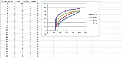
There you can conclude a few things:
The left motor has more acceleration and more top speed than the right one.
Since there is almost no drag (wheels are free spinning), as soon as initial drag is overcomed, speed reaches maximum value very quickly.
The acceleration instead, has a much more linear behaviour. Once initial drag is overcommed it can almost be said that the behaviour is linear in regards to throttle. This makes sense since throttle causes a current, and the torque of a motor is proportional to the current it consumes.
So what is the point of all of this?
You can do a PID controlled without this information, but if you use this information, you can generate a table where you have an approximation of the throttle required to set a specific speed or acceleration in a given motor. And this will greatly reduce overshooting and improve accuracy on the PID controller, since you are now working with real world data.
Will follow up on that.
Regards
![]() by MarcoP
by MarcoP
Tue Jul 03, 2012 5:47 pm
Seems the manufacturer has explained the difference between the left and right motors.
It seems that the brushes in most brushed dc motors do not have an symmetrical arrangement. Because of that they will turn slightly faster in one direction than the other.
Since motors on opposite sides of the Thumper rotate in different directions when it is moving forward this should explain the observed difference.
Regards
![]() by MarcoP
by MarcoP
Thu Jul 05, 2012 5:43 pm
Here you can see how the use of encoders enables precise trajectories. A circle in this example.
And here it enables constant speed despite increased load. (still needs some tweaking in the PID values)
Regards
![]() by SK
by SK
Tue Jul 10, 2012 8:08 pm

![]() by MarcoP
by MarcoP
Tue Jul 10, 2012 9:02 pm
Since this encoder reads the output shaft it can work with either gear ratio.
But actually this a bit of an improvised solution.
We will be launching soon motors with proper quadrature encoders that sit inside the housing so they will be sturdier.
I am working with these encoders so that we can release encoder version of the Wild Thumper code soon after we get them.
Regards
![]() by SK
by SK
Tue Jul 10, 2012 11:42 pm
I'm aware of a very expensive and complicated controller with encoder support available at Conrad germany, but never saw anyone use that:
http://www.conrad.de/ce/de/product/1916 ... ef=detview
Also, Pololu has motors with encoders:
http://www.pololu.com/catalog/product/2275
Are those what you're looking into?