Upgrayd's AX Darwin Project
Upgrayd's AX Darwin Project
![]() by Upgrayd
by Upgrayd
Thu Sep 01, 2011 12:57 am
I wanted to share the progress I have been making on my AX12 Biped project based on the DARwIn-OP project.
The mechanics of my biped are all custom design and fabricated by me to mimic the joint configuration for the DARwIn-OP.
The main controller for this robot will be a Gumstix Overo COM booted from a micro sd card with and an image of Linux version 2.6.36 and the GNOME desktop. This image also includes native development tools for c, c++ and python.
The software controlling this robot is all custom but heavily based off of the open source code released from the DARwIn-OP sourceforge page.

Overall Picture. From foot the shoulder the robot stands a hair over 1foot tall.

Close up of the feet.
Here are a two videos of the robots fist steps:
http://www.youtube.com/watch?v=tFE8Lseg6IY
Forward walking.
http://www.youtube.com/watch?v=D8nuekcSKko
Sidestepping and turning in place.
----
http://upgraydlabs.com/
http://upgrayd.blogspot.com/


![]() by Upgrayd
by Upgrayd
Thu Sep 01, 2011 12:52 pm
i-Bot wrote:That's looking really good.
Are the side steps and turns based on IK and a gait ?
Did you include these into the walking module, or add a new module.
Are the 5 AX12 in the torso mounted direct onto the backplate ?
The sidestepping and turning are both part of the walking module all using the same gait and kinematics engine.
The torso servos are all mounted directly to the backplate. The backplate in the images and video is temporary until I can get the material make the aluminum equivalent.
![]() by nunogato
by nunogato
Thu Sep 01, 2011 10:18 pm
First of all nice post and project
You mention that you have custom design and fabricated some parts to mimic the joint configuration of the DARwIn-OP but I see a big difference.
The knee servo on the DARwIn is connected with the upper leg, check this photos
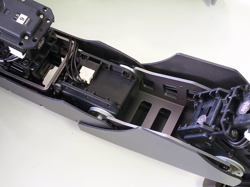
100_2038 by RoboSavvy, on Flickr
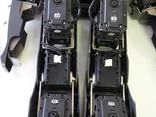
100_2033 by RoboSavvy, on Flickr
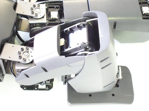
100_2041 by RoboSavvy, on Flickr
If you need any extra info about the DARwIn let us know

![]() by i-Bot
by i-Bot
Fri Sep 02, 2011 1:30 pm
If you conform to the general Darwin OP joint layout described here:
http://robosavvy.com/site/index.php?opt ... 1&Itemid=2
then changes to the software are parametric changes for the different dimensions and some setting of servo directions and zeros.
If you diverge from the Darwin-OP layout, then more work is required to modify the IK code.
The other thing is joint constraints, though that is more important form complex moves like getting up, rather than walking.
![]() by Tyberius
by Tyberius
Thu Sep 22, 2011 5:45 pm
i-Bot wrote:The other thing is joint constraints, though that is more important form complex moves like getting up, rather than walking.
Just to confirm, this is actually set via CCW & CW angle limits in the registers of the dynamixels, correct? I noticed that the dynamixel firmware upgrade script sets this for each ID.
![]() by i-Bot
by i-Bot
Thu Sep 22, 2011 7:40 pm
While the MX firmware installer has hardcoded limits which are set with firmware updates, this may not work for AX based robots. The dxl_monitor also sets the CW and CCW limits on RESET. Again these are hardcoded and must be changed to meet your configuration above.
There may also be value to adding some debug code to the action or walking modules to flag if limits are ever exceeded in custom configurations.
![]() by MOHIT JINDAL
by MOHIT JINDAL
Tue Nov 01, 2011 3:23 pm
I saw your blog. Can you tell me from where you got aluminium frames ?