Robobuilder Linuxified - adding an embedded linux board
Robobuilder Linuxified - adding an embedded linux board
![]() by marco
by marco
Mon Nov 21, 2011 5:55 pm
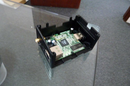
we at Robosavvy have been trying to get Robobuilder to carry an embedded Linux board. The Omnima - MiniEMBWiFi 320MHz Embedded Linux Board seemed perfect for the mission and we started to think how we could adapt the robot for it.
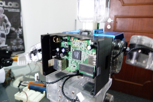
The first problem to be solved is the mechanical integration of the board on the robot. Our approach was to design a new backpack in order to make space for the Omnima board. The original backpack was just a few millimeters short of the needed size, so our hope was that we would be able to design a backpack with similar dimensions without compromising the robot's mechanical performance.
We designed the backpack with Google SketchUp and then printed it with a MakerBot - Thing-o-Matic 3D Printer.
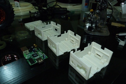
Take a look at one of the first prototypes:
The Omnina MiniEMBWiFi board goes underneath the Robobuilder control board.
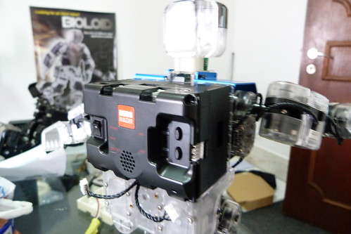
Close-up on the new backpack.
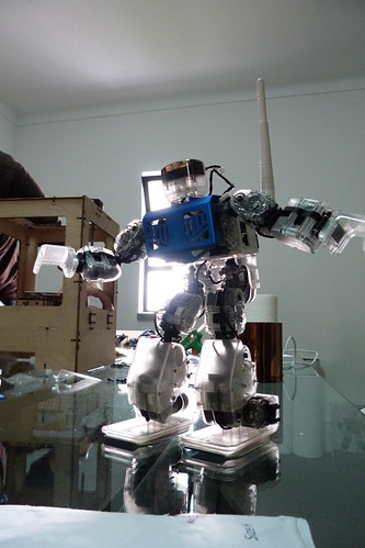
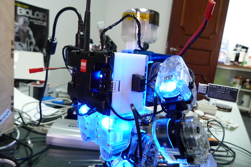
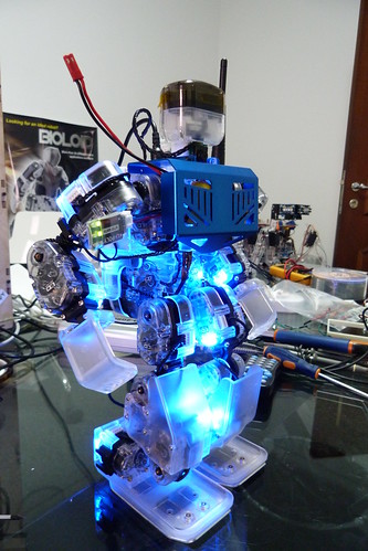
Robobuilder equipped with the Omnima MiniEMBWiFi in all its glory.
Right now another prototype is on the 3d printer to get tested (this one had a few mechanical bugs that are not visible in the picture).
After the mechanical part having been sorted out, we'll focus on the electrical connections and then on the software with the robobuilder doing new tricks.
Cheers,
Marco


![]() by PedroR
by PedroR
Thu Nov 24, 2011 12:39 pm
Omnima said - unofficially - that the board could be powered with up to 15V DC.
While this is true, the Power Supply to the USB devices is unregulated and Omnima forgot (or didn't realise) this.
Therefore we've plugged a Bioloid SMPS (12V) tot he Omnima and it did turn on. The only "minor" issue was the Webcam that was completely burnt.
The Omnima board offers great value for money - especially when running the latest OpenWRT - but we have the feeling Omnima didn't design the board themselves: they either bought the design or are sourcing it ready made.
Some key points about the Omnima that may not be obvious:
Running the latest OpenWRT Kernel (patched according tot he instructions here http://www.omnima.co.uk/forums/index.ph ... post&p=641 ) the board offers great features:
-- command line linux/shell (a familiar environment for many of us) which makes it easy to design your own custom solution.
-- most of the popular packages ara available via opkg including ssh server, proftpd, python, mjped streamer, UVC drivers (webcam support), FTDI and Prolific drivers, etc.
-- a web interface (Luci) is included where you can easily and quickly configure exactly how you want the Ethernet and WiFi port to behave (ie if the WiFi should be client OR host, setup all wireless settings including security, etc,)
-- Luci also offers a Graphical Interface to opkg letting you search and install packages from the Graphical interface as well as access to a number of other configurations.
(Luci is to Embedded Linux what Cpanel is for Webservers: it eases a LOT of the pain and grief involved in setting up and managing the day to day tasks)
-- There is a native serial port at TTL level (3.3V) which can be detached from the console although it will still occasionally receive messages from the Kernel for some reason.
The port can be reused to connect directly to many external devices (such as Arduino, or in the case of Robobuilder the BT socket to gain access to the Serial protocol of the RBC controller).
The latest batch of boards we've received from Omnima (now in stock and ready to be ordered) already comes pre loaded with this OpenWRT Firmware (the was compiled by us and is the one we're using on the Linuxified Wild Thumper and also being used in the development for Robobuilder)
On the downside (for this price there have to be a downsides
For example if you're using a Webcam, when you insert the USb2Serial device, the frame rate drops from 30fps to 4fps for no apparent reason (no data is flowing at all).
Marco should keep you updated as we progress
Regards
Pedro.
![]() by i-Bot
by i-Bot
Thu Nov 24, 2011 2:23 pm
http://uk.mouser.com/Search/ProductDeta ... QqJQ%3D%3D
On the USB performance, interesting the Prolific is also giving problems. I thought maybe increasing the latency value on the FTDI would help, because it sends a message to be processed by the driver at the latency timeout whether serial data is present or not. Prolific and the CDC devices like USB2AX only send when data is available. I am wondering whether the USB host controller is not too intelligent on the Ralink chip. Also later USB drivers have been optimised for high throughput and more intelligent controllers.
I will set up my USB analyser to look at what is happening if I have time. Which camera and hub are you using ?
![]() by marco
by marco
Thu Nov 24, 2011 5:49 pm
Regarding the cameras, I tested with a cheapo NGS Netcam-300 and a Microsoft LifeCam HD-5000. Fortunately it was the NGS that fried.
The hub was also a cheap thing that has no brand on it. I opened it up and it has only one IC: Terminus Tech FE1.1 USB 2.0 HIGH SPEED 4-PORT HUB CONTROLLER
The problem was described here. I replicated the setup on a regular laptop with Linux and no problems appeared. I also bet on some kind of low level stuff in the Omnima board that doesn't handle this setup very well.
![]() by MarcoP
by MarcoP
Thu Jan 19, 2012 7:09 pm
New Marco, same project.
I've picked up this project, so here are some updates:
P1000763 by RoboSavvy, on Flickr
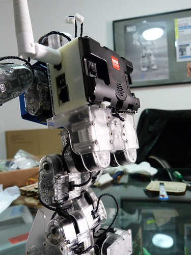
After a few iterations we have now a backpack that should be very similar to the final product.
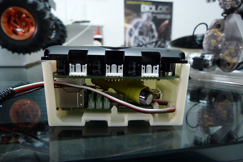
P1000766 by RoboSavvy, on Flickr
As you can see everything fits in nicely.
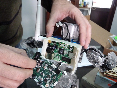
As part of this project our objective is to add vision capabilities to the RoboBuilder via a webcam.
Instead of the obvious solution of simply bolting on a webcam to the frame we have been tinkering around with the idea of placing the camera inside the head since some space is available.

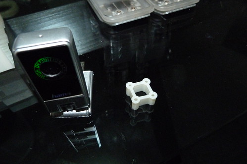
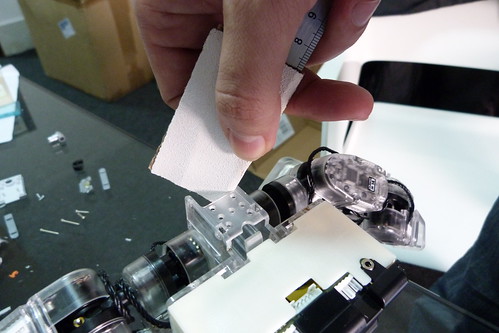
P1000748 by RoboSavvy, on Flickr
First strip open a brand new webcam.
But even in it's reduced form placing the webcam pcb in the head would require extensive modifications to the plastic head case.
Using the neck area was the next option, but clearances were an issue.
Solution: give the RoboBuilder a longer and more exquisite 3d printed neck:
P1000761 by RoboSavvy, on Flickr
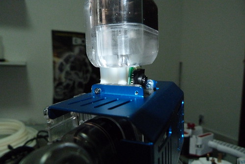
P1000762 by RoboSavvy, on Flickr
This creates an open area enough for the camera to poke trough and to have a clear vision forward or even at a downward looking angle.
P1000751 by RoboSavvy, on Flickr
The only modification needed in the robot is to shave maybe 0,5mm of the frame on each side of the neck to make space for the pcb.
P1000768 by RoboSavvy, on Flickr
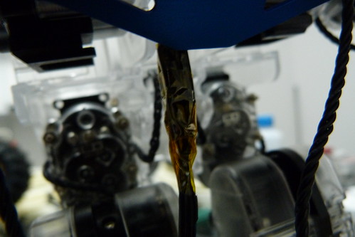
The maybe not so easy part of this mod is to re-solder the usb wires coming of the webcam to a usb extension cable, but in our opinion it is worth the effort given the clean look of this mod.(connections wrapped in heatshrink and kapton tape)
P1000754 by RoboSavvy, on Flickr
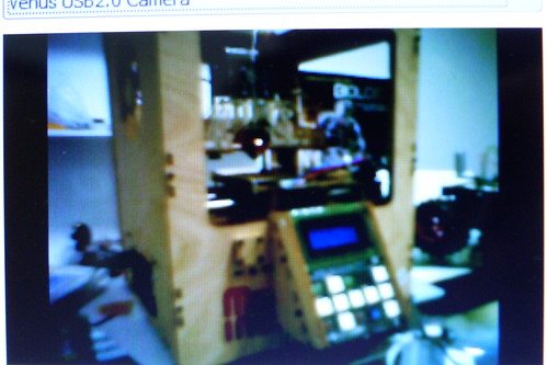
Here you can see the image coming off the webcam (notice our pretty 3d printer that just happened to be in frame).
More to follow
![]() by i-Bot
by i-Bot
Thu Jan 26, 2012 12:58 pm
http://uk.mouser.com/ProductDetail/Roving-Networks/RN-SMA-S-RP/?qs=sGAEpiMZZMukHu%252bjC5l7Yfc6iP7FD01pr%2Fk5lSTWB2o%3D

![]() by MarcoP
by MarcoP
Fri Jan 27, 2012 5:21 pm
Actually we were more concerned with the arm colliding with the antenna if it is turned all the way around, but based on your suggestion we found this antenna, that should solve both problems.
ParanoidAndroid, the webcam can be found here:http://uk.shopping.com/Hama-Hama-Pocket-Webcam/info .
The image shown in the post is a bit blurry because we didn't refocus the camera after installation.
The focus ring is not accessible when the camera is assembled, but it can be accessed when it is disassembled, which is great to refocus the camera to a closer or longer range depending on the intended application.
Regards
![]() by MarcoP
by MarcoP
Tue Jan 31, 2012 12:52 pm
So here are the updates:
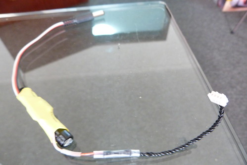
The dc converter soldered to the wCK cable. Still need to get right angle dc connector to improve clearances.
Each wCK cable is cut in half to yield two power cables.
Despite not being used, the 2 data wires are left on since people normally pull on the cable to get it out, so this way it is more resilient.
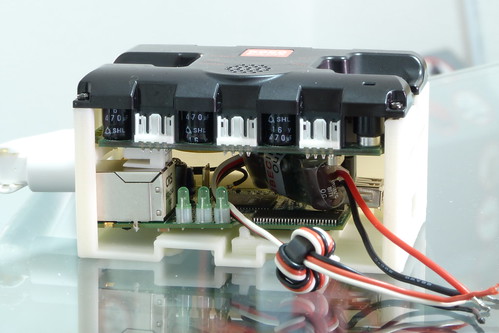
The black backpack. Notice there is a small tab in the lower right to clinch the power cable to provide strain relief.
We will probably offer the option of color, or even transparent plastic to the customer.
This black one almost seems factory made.
Regards
![]() by MarcoP
by MarcoP
Mon Feb 06, 2012 6:59 pm
Getting back on this.
(Don't mind the array of extra wires)
I'm doing simple blob tracking. For now just turning side to side to keep object in sight.
Will post a video later.
As a curiosity to those who might not know this: issuing commands on the serial port can override currently running motions. For example if you use the remote to turn, and press stop during turn the motion continues, but if you issue the same commands in serial port it stops mid motion.
Regards
Marco
![]() by MarcoP
by MarcoP
Mon Feb 13, 2012 6:36 pm
Just a quick update.
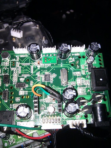
This is how we connect the serial to the bluetooth header. (Orange is RX)
Ground is not connected because the omnima and RBC already have a commom ground via the dc-dc converter, but you can connect it just to be on the safe side.
Regards
Marco
edit: had wrong pinout
![]() by l3v3rz
by l3v3rz
Mon Feb 13, 2012 11:37 pm
Also I think I can connect directly to wckBus and see I/O. Do you see the same ?
cheers