Robosavvy's CNC
Robosavvy's CNC
![]() by MarcoP
by MarcoP
Fri May 18, 2012 5:58 pm
As part of our expansion we got a cnc.
http://www.forumcnc.com/cnc-forum/portal.php
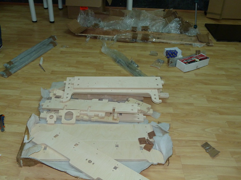
It is designed by someone called Tonio who has a boat workshop in Southern Italy and as a hobby he designs CNC's. His online forum is very active albeit in Italian. We bought the pre-cut beautiful wooden CNC kit from him, the metal linear guides and bearings from an Italian online store that he recommended and the steppers and drivers from Ebay.
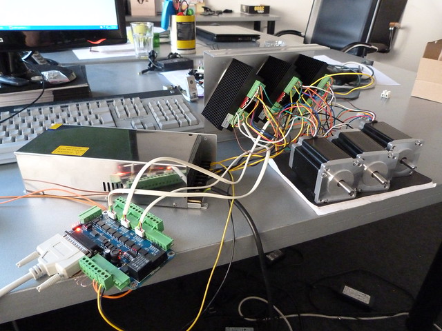
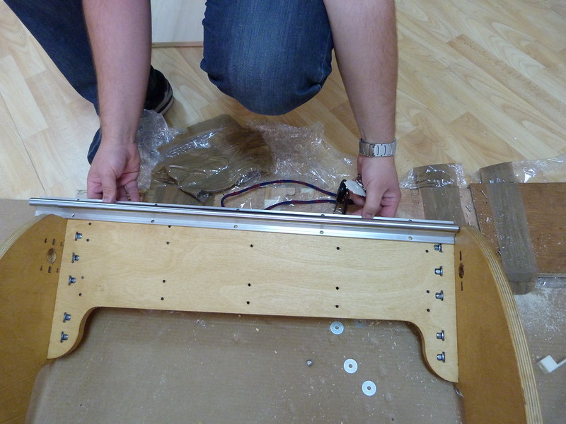
We are still waiting on the frame and rails but we got all the electronics, so i was able to assemble everything for testing.
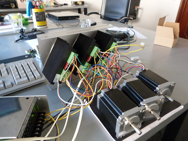
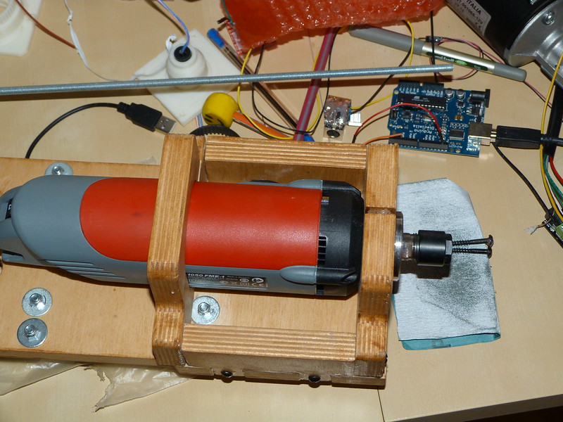
The steppers are NEMA 23's, 3.1Nm running at max current (4.2A).
The controllers are bolted to an improvised heat sink. Barely got warm despite full power.
They do get a bit hot but well within limits.
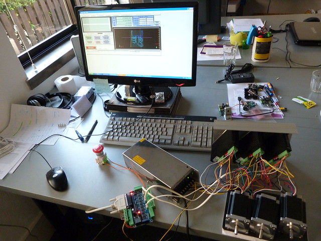
Had it running a demo on mach3.
Now time to learn how to use it
Will update when it's completed.
Regards

![]() by PaulL
by PaulL
Sat May 19, 2012 4:00 pm
![]() by MarcoP
by MarcoP
Mon May 21, 2012 12:09 pm
We wanted to build one from scratch but we need a cnc in the short term for a project we are doing so i just got a kit for the electronics, wood and rails.
Travel is around 50*40cm. (but we still don't have it here).
The electronics/steppers are also a bit overkill, but long-term that will allow us to move them to a larger cnc we might design.
Our chopper driver goes up to 4.5A but i have it set at 4.2A(stepper rated current)
However i am using microstepping and from the manufacturer information the 4.2A is the peak current. RMS value is around 3A. Our power supply has 11A at 36V so it seems if in the worse case scenario will be 9A.
The demo i was doing was a 2D cut so the Z axis barely moved.
The power supply barely got hot.
Did you measure your output voltage when flat-out in all axis? Maybe your power supply is dropping voltage, causing the missed steps.
Rgds
![]() by PaulL
by PaulL
Thu May 24, 2012 10:48 am
Haven't measured the voltage... Switching supply as well. When it's flat-out, the heaviest loaded axis will bail out of the move, and sit and "scream" from the signal (it'll pick back up on the ramp-down at end of move), the other 2 don't miss a beat.
I'd bet the voltage sags at that load. A bigger power supply would surely fix the problem. I can rapid that same axis alone, or with one other in motion, but not all 3.
![]() by MarcoP
by MarcoP
Tue Jul 31, 2012 2:30 pm
http://www.flickr.com/photos/robosavvy/7317676292/in/set-72157630005223770

[img]
http://farm9.staticflickr.com/8168/7339 ... 1107_c.jpg[/img]
<object type="application/x-shockwave-flash" width="800" height="450" data="http://www.flickr.com/apps/video/stewart.swf?v=109786" classid="clsid:D27CDB6E-AE6D-11cf-96B8-444553540000"> <param name="flashvars" value="intl_lang=en-us&photo_secret=2e57cc695c&photo_id=7350031442"></param> <param name="movie" value="http://www.flickr.com/apps/video/stewart.swf?v=109786"></param> <param name="bgcolor" value="#000000"></param> <param name="allowFullScreen" value="true"></param><embed type="application/x-shockwave-flash" src="http://www.flickr.com/apps/video/stewart.swf?v=109786" bgcolor="#000000" allowfullscreen="true" flashvars="intl_lang=en-us&photo_secret=2e57cc695c&photo_id=7350031442" height="450" width="800"></embed></object>
[img]http://farm8.staticflickr.com/7223/7165100199_c8dda33df9_c.jpg
[/img]

Regards
![]() by MarcoP
by MarcoP
Tue Aug 28, 2012 7:33 pm
After a few weeks of just running it in the floor so that i get more confortable with it we finally decided to move it to it's final location.
One of the problems we had to solve was how to get a 11cm diameter in the table where the cnc is going to run the vacuum hose.
The solution: use the cnc to cut it out:
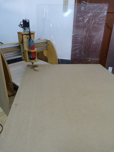
Seems strange to use the cnc to cut something much larger than itself.
But still a good result.
The table itself was made out of 19mm thick MDF with some re-enforcing wood beams underneath.
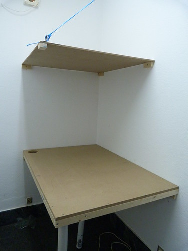
It was secured to 4 pieces of wood that were previously bolted to the wall and has one generic table leg in the corner.
It is very stable. I was able to stand on it to do the top section.
There i used a 10mm thick MDF board. We have also some 1mx1m acrylic sheets, that should enable us to enclose it completely.
More to follow.
![]() by MarcoP
by MarcoP
Thu Aug 30, 2012 4:27 pm
So here it is in all of it's glory:
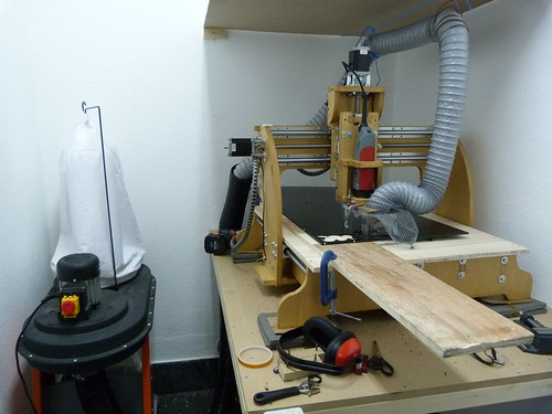
Notice the oversize vacuum. We got something larger than what the cnc needs since we are planning on running other tools that need vacuum as well, not to mention another smaller cnc.
I also improvised a simple skirt to go around the tool to contain the swarf (to the uninitiated, it's the shavings that come of the material.)
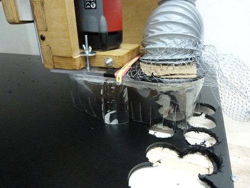
Made out of cut soda bottles and rubber bands. El cheapo style.
Of course it's just a quick fix. Planning on doing something much better later on.
Still it works so well that i had to place a net over the vacuum hose because the pieces i was cutting kept getting sucked in.
Here i am doing tests cutting material.
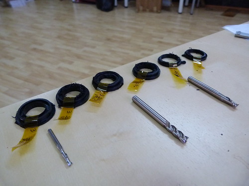
It's HDPE plastic. It's one on the most widely used plastics for these applications because of several advantageous characteristics, such as: good strength, low friction, chemical resistance and good machinability .
These show several tests, going from right to left, with different end mills, feedrates and tool rpm.
Results have been improving.
The last one was almost perfect. Just not the right shape because i used a 3mm bit with Gcode created for a 6mm bit.
Rgds
![]() by MarcoP
by MarcoP
Fri Sep 07, 2012 6:18 pm
So now i wanted this ready for proper use.
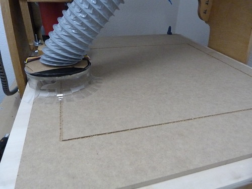
One of the problems we got is that the build surface is not levelled. This is something we are familiar with from 3d printers.
The "problem" is caused by the fact that wood is never going to be perfectly flat.
However unlike a 3 printer the cnc can shape the world to it's needs. In other words, the cnc can level the build surface, by doing continuous passes back and forward over the build surface:
Ignore the side cuts. They were caused by the drill going outside the designated area because of a problem we later discovered was because of wireless network latency.
We have been using a pc to control the cnc, and we control that pc in turn with one of several laptops over a Remote Desktop connection. Usually over an ethernet cable to get a more stable connection, but this time it was over wireless, wich does not seem a good idea.
After this ruff cut, a more precise path was cut out, to get a clean outline.
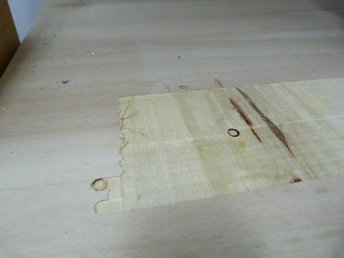
However the objective here was not to use this as the build surface but instead to use if as a pocket where to insert a sacrificial wood board.
This was cut out with the same dimensions as the pocket bellow out of mdf:
If fits tightly so i dont have to worry about it moving around:
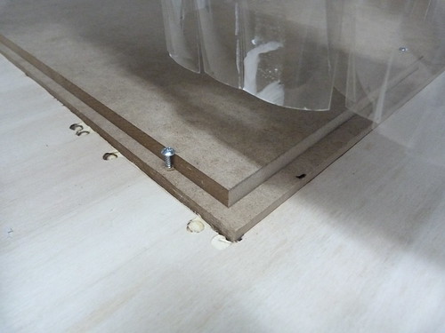
This gives me a piece of disposable wood that handles screws better the plywood underneath.
Another advantage is since i can swap them out quickly, i can cut out shapes in these boards to accommodate parts, which enable us to machine both sides of a part, without having to worry about alignment from one side to the other.
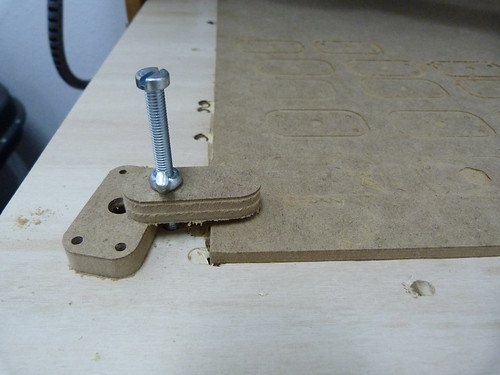
Another thing i wanted to add was clamps to secures the larger materials.
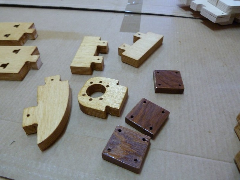
I wanted something that could be reused over and over again without damaging the wood, so i designed these holders in inkscape to hold a nut and washer:
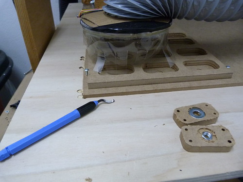
I drilled the main wood board and then screwed these parts under the holes.
(Also note the de-burring tool)
I can now quickly add or remove clamps, without even needing to access the bottom of the machine, so this should save us some time.
Regards

![]() by MarcoP
by MarcoP
Wed Mar 06, 2013 7:47 pm
We are getting to a point where the cnc is used often enough to justify spending the time to facilitate it's use.
As shown before we are using a Kress, and we manually turn it on and off which get's old pretty quick.
Out breakout board has a relay output to enable to turn thins on and off. So we did this electrical box, which is basically a relay to turn the kress on and off with software.
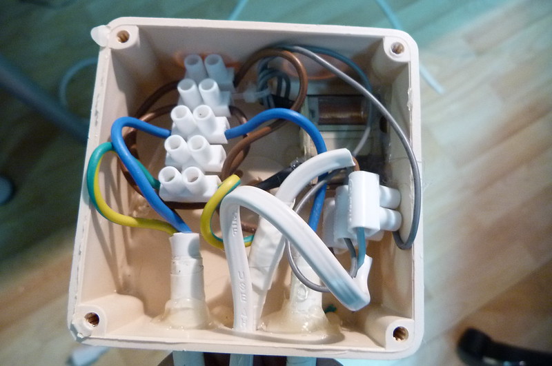
Another important advantage is that this way the spindle also stops if we hit the E-Stop.
Another thing we are using is a air jet to blow aluminium chips away and mist to lubrication. This was also being started and ended manually with a manual air valve.
So we got an electric valve, that since was not designed for air hoses required a lot of fittings to be able to connect to the air hoses.
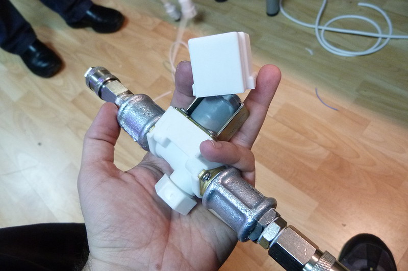
The fitting weighs more then the valve itself ;P
We use the same output for the spindle to turn on the solenoid valve.
The shop was out of male to male adapters so we designed on in a few minutes and printed it in one of our 3d printers.
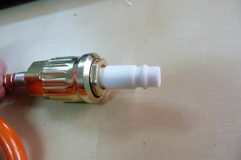
Wont be as durable, and if it breaks under pressure it's contained in metal no issues there.
You just got to love 3d printers!
Regards
![]() by limor
by limor
Fri Mar 29, 2013 3:08 pm