Building humanoid similar to Asimo and Qrio
![]() by limor
by limor
Mon Dec 31, 2012 7:47 pm
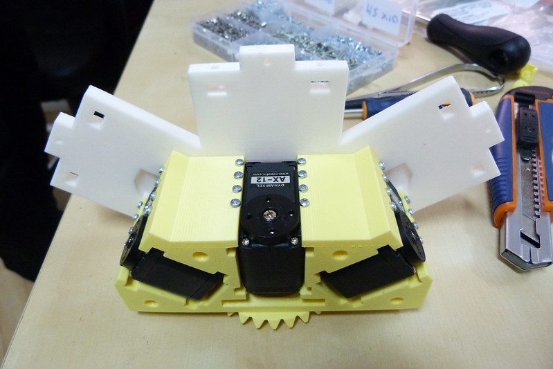
Another issue is that the the AX18 servo's width is indeed a little less than 26mm but when printed, the internal cavity width is 25.7. possibly because of the support material leftovers. so need to re-print without support material otherwise need to modify the servo cavities to add a bit of space.
.jpg)
.jpg)
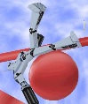
Next I tried to print the upper torso part. it would be great if it can be printed without support material simply with that big bevel gear facing up. so the part was sliced to expose only the problematic gear. the bottom part was cut off because effectively only the top 90 degrees will ever be used to rotate the torso.

The result on first look is not bad. The broken line was caused by a couple of missed steps in the Z axis. The printer has been running for weeks and needs some tweaking. The top part of the hole is distorted because of the bridge that needs to be created. it is normal and it can be fixed by filing the hole smooth.
.jpg)
.jpg)
.jpg)
.jpg)
.jpg)
But here comes a serious problem of the upright printed bevel gear. it is oval shaped and slightly distorted. so it doesnt fit onto the other printed part which was printed horizontally. The distortion can be caused by the problematic Z axis on this printer or by the PLA which takes ages to cure. don't care. it means that the bevel gear can't be printed upright.
.jpg)
.jpg)

![]() by PaulL
by PaulL
Tue Jan 01, 2013 10:16 pm


![]() by limor
by limor
Sun Feb 24, 2013 11:42 am
I've spent hundreds of hours on this project and he is dedicated to make our debut of the robot with a dance at the upcoming Gadget Show Live 2013 in Birmingham (April)

![]() by limor
by limor
Mon Feb 25, 2013 8:29 pm

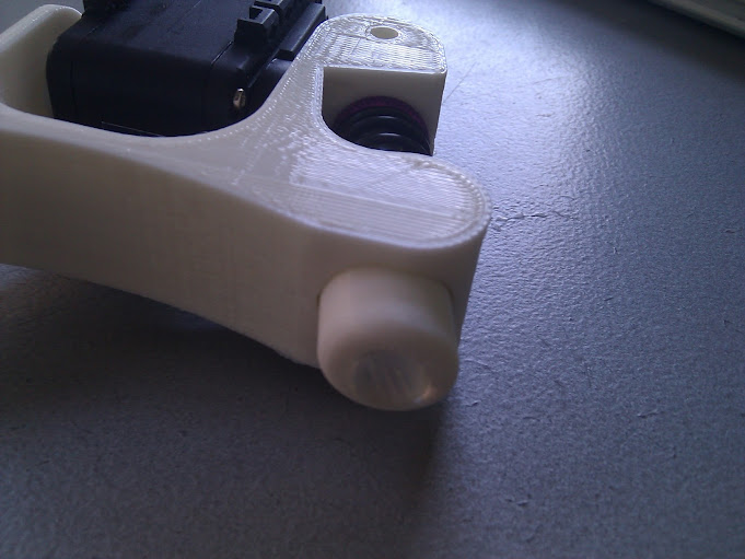
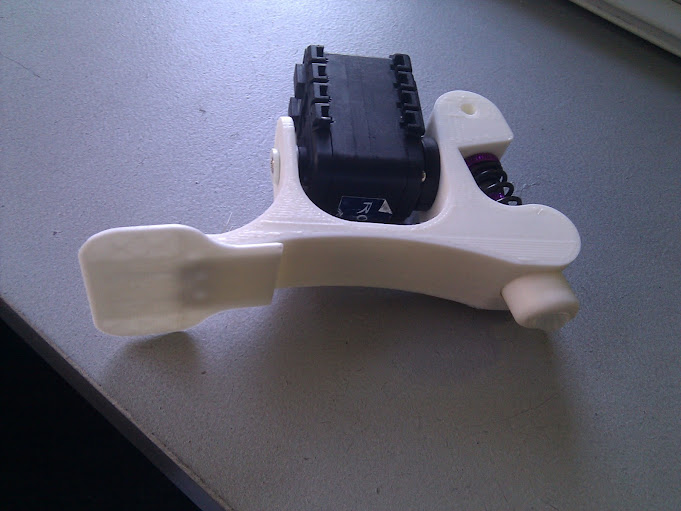
New foot has a spring loaded toe for better ground traction and human looking walk. It also has a suspension heel for the same reasons and for easier physics simulation. There's a little rubber half-ball at the tip of the heel.


![]() by limor
by limor
Fri Mar 29, 2013 3:12 pm
We tightened the fishing wire a bit too much. The servo is rated for 12kg pull at 1cm distance from axis. so by creating a permanent pull of over 10kg, it means that any additional external torque will be added to the 10. which means it creates needless excessive side force on the shaft.. it also caused the pulleys to touch (which later burnt the mosfets of the servo) but this is because the 3D printed pulley internal hole radius was too big compared to the metal axis in the knee. conclusion- the clamping and tightning of the wire should be as small as possible while ensuring there is not flex in the cord.
![]() by limor
by limor
Sun Apr 28, 2013 11:35 am
I presented him last week at the Next Berlin conference in front of about 600 people. hopefully they will upload the presentation to youtube.
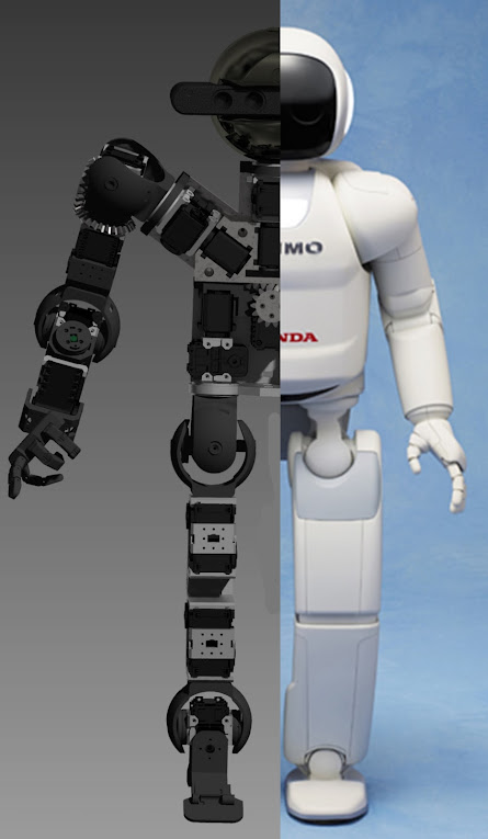
One of key points I discuss in the presentation is that the design of franky's joints and proportions matches those of Asimo. We will design a first shell for Franky that will look a bit like Asimo. Honda spent $150m on their humanoid efforts, so they must know a thing or two about humanoid robot design
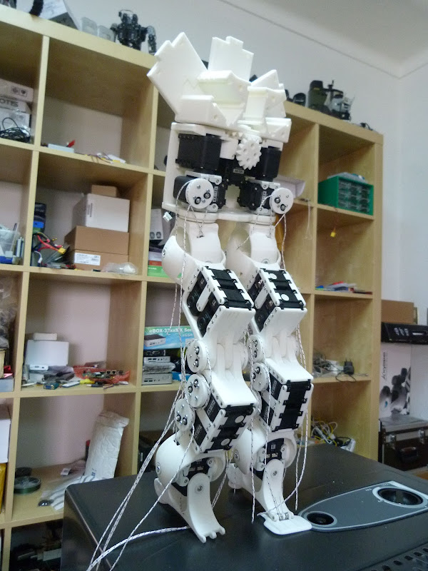
Here he is shown with a Makie 3D printable doll sitting on him
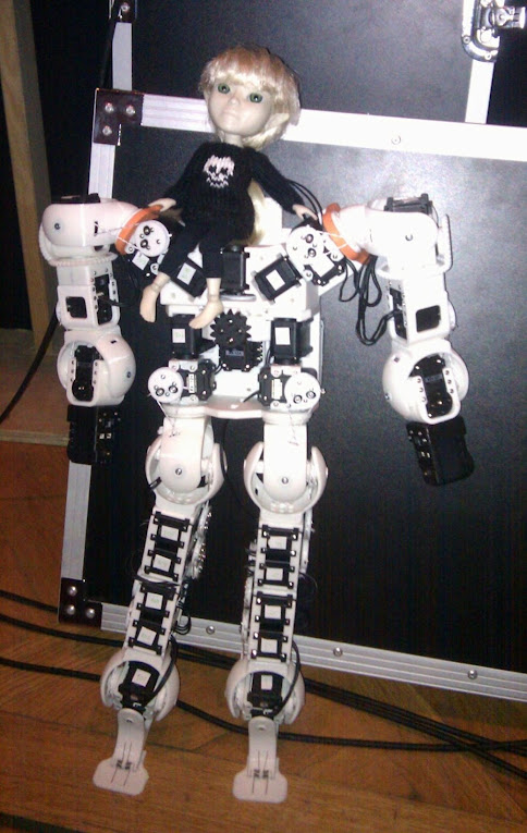
He can't quite walk yet. that will be the next challenge.
![]() by siempre.aprendiendo
by siempre.aprendiendo
Sun Apr 28, 2013 11:54 am
Anxiously waiting to watch him walking
