UFOBOT - Heavy duty self balancing research robot
UFOBOT - Heavy duty self balancing research robot
![]() by limor
by limor
Tue Sep 11, 2012 10:56 pm
We realized that what the world needs is a self balancing robot that can take on heavier loads like a laptop, big battery and kinect.

Some CNC cutting of HDPE plastic..


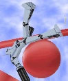
Basic structure ready for initial testing..

Some CNC cutting of HDPE plastic..
Basic structure ready for initial testing..


Updates
![]() by Cláudio Brito
by Cláudio Brito
Mon Aug 26, 2013 4:13 pm
Electronics and 2nd floor added.We are using an arduino mega as microcontroller plus additional electronics such as motor driver, accelerometer and gyroscope.
Last edited by Cláudio Brito on Tue Aug 27, 2013 5:27 pm, edited 1 time in total.

Updates (cont.)
![]() by Cláudio Brito
by Cláudio Brito
Tue Aug 27, 2013 5:27 pm


We have instaled one low cost optical encoder inside the motor. This is how the signal looks like at 92 rpm:


We intend to add 3 more so we can achieve a resolution around 1200 counts per revolution. This will allow us to do a precise speed control at low speeds.
Other approaches were made:
1. Magnetic encoder inside the motor using hall effect sensor plus the original encoder magnet;
2. Optical encoder mounted on the wheel;
- Option 1 resulted in a very inconstant signal, probably due to interference of the motor magnetic field;
- Option 2 worked but was not the most robust alternative since any oscillations or dust in the sensor would result in bad performance. Also had a limited resolution;
This is the analog comparator circuit used for the encoder:

About the software...
A Kalman filter was implemented to filter and combine information from the gyro and the accelerometer to obtain a good angle estimation.
The first approach used to achieve balance was a PID controller based on a static equilibrium angle and the current angle. This was a very limited approach since
any change on the center of mass would cause the robot to fall, but this first simple step was fundamental to see the controller behavior on the easiest case.
So far, this is how it behaves:
phpBB [media]
A more general algorithm is currently being developed, so the robot can learn by himself the equilibrium angle.