RoboSavvy Designing and Fabricating a 1m tall Humanoid
RoboSavvy Designing and Fabricating a 1m tall Humanoid
![]() by PedroR
by PedroR
Thu Oct 25, 2012 11:14 am
RoboSavvy is currently developing a 1m tall Humanoid for a UK University as part of a consulting/research project.
The Humanoid will be based on Robotis servos (MX series) and will include advanced features such as onboard i7 PC, 24+ degrees of freedom, advanced Vision systems and Physics simulator.
The whole project has been divided into several steps, which we'll be blogging about over the coming weeks.
We're currently on Step1/2 which is CAD Design and BOM assessment.
The next steps will Involve the actual Fabrication of the frames (check our progress cutting metal with our in house CNC) and Development of the Robot Software and Physics Simulator.
A Body shell is also planned, incorporating clever, hybrid fall management solutions combining software and hardware features.
Over the coming weeks we will be sharing with the community our progress and our findings and progresses addressing the challenges of the added size, weight, power consumption and fabrication.
Regards
Pedro.

![]() by TiagoR
by TiagoR
Wed Oct 31, 2012 10:28 am
Since the robot we are developing is based on DARwIn-OP the first approach was to keep the design of the structure and increase the size of the brackets, resulting in the following parts.
Bracket from Hip to Knee:
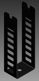
Hip2Knee
Bracket from Knee to Ankle:
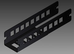
Knee2Ankle
Just by looking at the first bracket it is possible to see that with the weight that it will support it will probably bend and compromise the legs.
Because of that we decided to add a reinforcement:
LegReinforcement
The resulting leg looks currently like this:
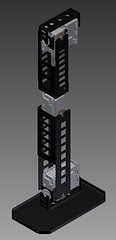
LeftLeg
Regards
Tiago

![]() by Novice
by Novice
Thu Nov 01, 2012 10:48 am
Be carefull,the lenght of the leg is too long.You have to use the high power servos for that, otherwise the ones may be burnt.The Darwin-OP is good disigned and counted robot, I think you could change the basic dimension of one plus or minus 15-20% maximum.If more- you have to refind new datas for everything.
Please note, even though you did the size and the weight of the robot small different agaist of the its firm size, it is the reason why the robot cant do the standard movements from the firm labruary, be ready to design all the movements and write your own new basic labruary.
Best regards
Oleg
![]() by limor
by limor
Thu Nov 01, 2012 11:50 am
Thank you for your suggestions.
Indeed the servos are being replaced in most cases by the more powerful MX-64 and MX-106.
In some cases such as the knees it is obvious that 106 needs to be deployed while in other places such as the 3 axis of the hip, it is not so clear if MX28 or MX64 will be needed.
The CAD model produces all the intertial data of the robot and it will be inserted into a simulator (V-Rep most probably or Ezphysics or Gazebo). In the simulator the plan is to run the Gait generator of Darwin-OP, adjusted for the model.
The movements of the robot determine what power the servos need to have.
1) Darwin-OP Gait generator
2) Getting up sequence from laying on front and back - very tricky
3) manipulation of objects using hands
A simulator will never be able to actually represent reality but if the simulator shows that the range of torques for the given motions is within say 70% of the specs of the servos, then it is likely that the real robot will be able to perform the motion in real life
![]() by TiagoR
by TiagoR
Fri Nov 02, 2012 5:46 pm
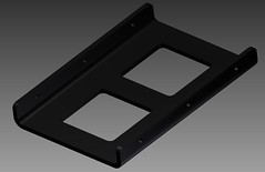
Today I bring some details on the torso construction.
First a perspective of the front and back of it.
Front:

Back:

As you can see in the previous images the torso is divided in essentially 5 parts: Hips, batteries, electronics, motherboard and Arms & Neck.
The hips part consist in the remaining degrees of freedom of the hip that are not on the legs picture, and right above them is the batteries room.

Next is an empty room where some of the electronics needed, but not yet built will be placed. On top of that is the room where the Motherboard will fit.

Motherboard:

Finally is the room where the Neck and shoulder servos will fit.

Best Regards
![]() by SK
by SK
Sat Nov 03, 2012 1:46 pm

![]() by TiagoR
by TiagoR
Tue Nov 06, 2012 11:19 pm
First of all I am sorry for the late reply.
We are using Nimbro-OP not exactly as a starting point but mostly as a reference.
There are some reasons for that, such as we want a slightlly taller robot, and we still don't know if we will be able to build the carbon fiber parts or not, among other reasons.
Best Regards
TiagoR


![]() by TiagoR
by TiagoR
Wed Nov 07, 2012 10:34 am
Thank you for your interest.
We are planning on having 5 degrees of freedom in the hands:
-> Wrist
-> Thumb
-> Index finger
-> Middle finger
-> Ring finger and Pinky (actuated by the same servo)
So the fingers are under-actuated in the sense that either you move the finger or you don't, you can't close the finger arround itself like humans do for example, you can only close it fist-like.
The rest of the arm has for now 3 degrees of freedom (2 on shoulder, 1 on elbow), comparing to a real human it is lacking and it is restricting when you are working on a plane, for example on top of a table.
We will try to explore the possibility of adding a servo before the elbow which would increase significantly the working area on a plane.
I hope this answers your question.
Best regards
TiagoR

1m Humanoid - three questions
![]() by firemonkey
by firemonkey
Mon Nov 12, 2012 8:31 am
3 questions immediately occur to me, the first two are related to "would this be capable or safe of tactile human interaction":
- are you planning any sensors around the body to detect "foreign body" proximity?
- are these actuators, or some control algorithm, you are planning capable of detecting "externally applied torque"? i.e. capable of detecting object collision, and thus capable of varying their "motion prerogative" (in a control loop) when a human is holding and moving them?
- what's the estimated cost?

![]() by TiagoR
by TiagoR
Mon Nov 12, 2012 7:03 pm
First answering to mantrid, it all depends on how you are building the ankle: how many degrees of freedom , type and dynamic of the actuators, and sample time.
The more actuators you have the more feedback signals you'll need, therefore bigger processing power.
Same with sample time, smaller sample time, closer to reality, bigger need of processing power.
Unfortunatly i can't give you a much better answer than this.
