RoboSavvy Designing and Fabricating a 1m tall Humanoid
![]() by limor
by limor
Mon Nov 12, 2012 10:59 pm
"would this be capable or safe of tactile human interaction"
Yes it is designed for human robot interaction. However, it is capable of delivering a huge amount of force so as Spiderman's uncle said, " with great power comes great responsibility ".
- are you planning any sensors around the body to detect "foreign body" proximity?
lots of FSRs on hands and feet. For this particular project we didn't put ultrasonic sensors or LIDAR but it is not to say that it can't be easily added. If you are a researcher and need a large size humanoid please lets discuss your needs.
- are these actuators, or some control algorithm, you are planning capable of detecting "externally applied torque"? i.e. capable of detecting object collision, and thus capable of varying their "motion prerogative" (in a control loop) when a human is holding and moving them?
The MX series servos have torque control and provide external current/torque estimation feedback although no proper torque measurement. If you search this forum and google you will find many example of compliant robot behavior using dynamixel servos. Additionally IMUs can give indication of external impact.
- what's the estimated cost?
The robot is a framework for customization. The price varies depending a lot on high value components such as embedded PC, servos, cameras, sensors etc. These may depend on performance requirements such as motions, payload, on-board computation, autonomy time etc. The target audience are HRI researchers, Robocup kid and adult size teams, and any other researchers needing a low cost large size custom humanoid.
If you are a researcher looking for a custom humanoid robot please contact us

![]() by TiagoR
by TiagoR
Wed Nov 14, 2012 7:04 pm
Today arrived the motherboard we will be using on the robot.
Here's a picture of it.
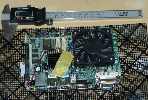
RealMotherBoard
Best regards

![]() by Novice
by Novice
Thu Nov 15, 2012 1:15 pm
In that case a weight of the robot is more than one kiloton
Look at the sample of Robobuilder company and lets use the experience their Titan..It looks like an invalid when it walks, dont duplicate their mistakes.
Wish you a success!
![]() by mantrid
by mantrid
Thu Nov 22, 2012 2:23 pm
TiagoR wrote:Hello all
First answering to mantrid, it all depends on how you are building the ankle: how many degrees of freedom , type and dynamic of the actuators, and sample time.
oh - sorry - from all the images and stuff I thought you'd designed it already.
Good luck with the gadget show - a pity its not at the NEC.
![]() by MarcoP
by MarcoP
Wed Nov 28, 2012 7:53 pm
For the main structure of the robot the original plan was to use aluminium.
However we also wanted to evaluate carbon fiber because it's supposed to be stiffer and lighter for the same amount of strength.
So we got a small board (foam cored) and tried to cut it in the cnc:
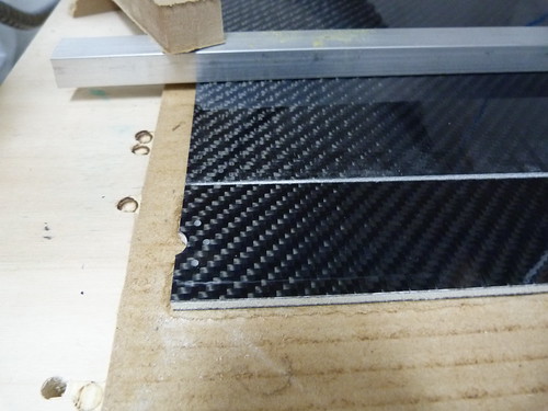
We were amazed with the quality of the results.
Perfect edges, in the first try. We were expecting the edges to be ragged, but they were smooth.
As comparison it took forever to get aluminium cutting right.
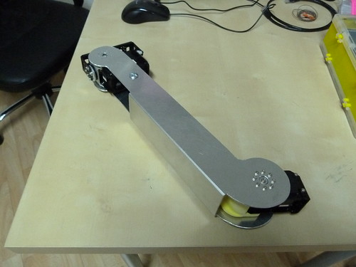
Then on to testing:
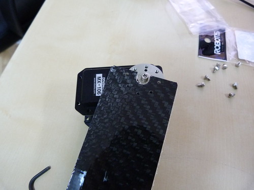
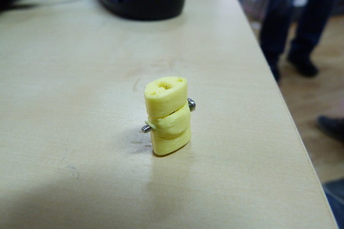
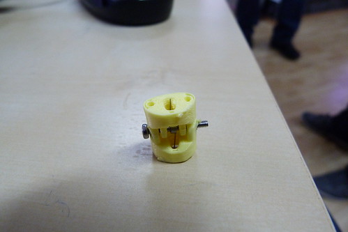
We assembled it in a MX106. Just to check the fit. However we were more interested in knowing how much torque we could put on the carbon fiber before it failed.
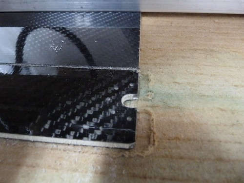
Not to risk the servo, we tried to screw the carbon fiber to a piece of wood:
We then used a scale normally used to weight luggage to pull the other end of the carbon fiber piece (length about 30 cm). By reading the value in Kg and multiplying it by 30 we get the torque in KgCm.
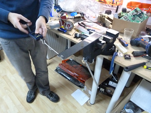
Just a few Kg were enough to pull the screws from the wood. So carbon fiber 1 - wood 0.
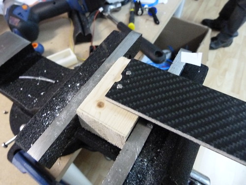
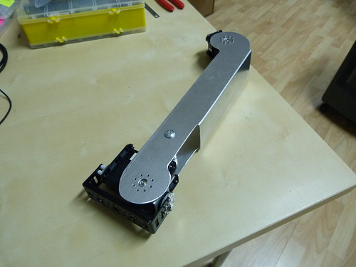
So we moved on to aluminium.
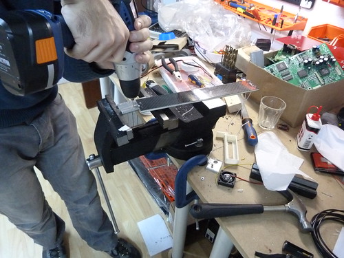
We used 2,5mm metal screws. But not from robotis. general purpose ones.
When we started to pull, this time the screws themselves bended. This uneven force did do slight damage to the screw holes in the carbon fiber.
So we widened the holes to 3mm, and used a nut on the other side.
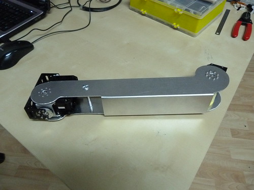
Still the screws bended a bit which might have accelerated the failure. Still we kept pulling until the carbon fiber failed. This was at about 6Kg, or 180KgCm.
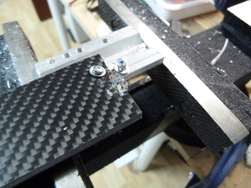
Given the fact that with just two screws, the carbon fiber held to almost twice the rating of the MX106 servos we feel very confident that it will be the best option. In the robot we will have 8 screws to distribute the load, so 4 times less load on each screw, which also should prevent them from bending.
For the more CNC inclided we used a 4 flute 2mm carbide slot drill. From what i have read online it's not a good idea do breathe in carbon fiber dust, however out setup directs all of the air that goes trough the vacuum filter directly outside.
Regards
Marco
![]() by MarcoP
by MarcoP
Thu Nov 29, 2012 2:40 am
We have a flexible air hose connected to a large vacuum : http://robosavvy.com/forum/viewtopic.php?p=35277#35277
The vacuum has large fabric filter. However some dust always get trough. So what i did was to use a large plastic sleeve over the filter and use an air hose to direct outflow air directly outside (empty lot in the back of the shop).
With this setup, by using the plastic skirts all the dust get sucked up into the vacuum, and any particles getting trough the filter will go outside.
The reason i know this works well is that whenever i leveled the table i would get a burning wood smell in the shop, but that does not happen with the new setup since all the smoke is sucked outside.
Regards
Marco
![]() by mantrid
by mantrid
Thu Nov 29, 2012 12:52 pm
Here is a link I've used in the past if anyone is curious about using
the material:
http://www.easycomposites.co.uk/Categor ... abric.aspx
The ability to buy a small amount of various samples and their starter kits is very helpful.
The dust shouldn't be much of a concern if dealt with as here. After all
alluminium dust has it's own safety issues - (fire - explosions etc)
I'm not so sure about expelling the dust out of the window though ...
![]() by MarcoP
by MarcoP
Thu Nov 29, 2012 4:20 pm
We did get the carbon fiber from that site.
Regarding the dust, of course we are not simply blowing it out the window.
The vacuum has a good filter. Of course a few fines particles will get trough.
Not trying to shift the problem to some else.
But between breathing it in, in a confined space and venting it outside where no one is nearby, the second option seems the best.
Regards
![]() by TiagoR
by TiagoR
Tue Dec 04, 2012 6:29 pm
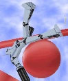
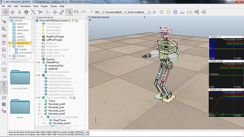
We are working in implementing the robot in virtual reality using a physics simulator and the CAD parts we built before.
The program we are trying is called V-REP, it possesses several calculation modules such as the already mentioned physics simulator, but also inverse kinematics module and colision module.
We exported the robot CAD files into two models, a simpler one to start getting used to the program and apply a simple gait, and a more complex one, with all the degrees of freedom (for example the simpler one doesn't move the hands).
Here are some pictures of the results.
Simple Model:
V-REP0
Complex Model:
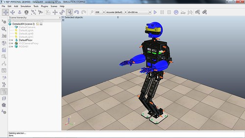
V-REP1
Best regards
![]() by TiagoR
by TiagoR
Fri Jan 04, 2013 12:16 pm
It is indeed open in the back side, so not only can it twist easily, but can also suffer from barreling on the sides of the leg and collapse.
We are exploring two solutions for that:
1 - placing a metal frame behind
2 - using carbon fiber on the sides with metal frames in the front and back
Best regards