Torque sensing via current in analog servos.
Torque sensing via current in analog servos.
![]() by MarcoP
by MarcoP
Mon Dec 17, 2012 6:42 pm
Hi guys
As part of out 1m humanoid robot project we are developing several solutions to some common problems in robotics.
The fingers in the hand are supposed to be actuated by several servos.
Due to size and weight constraints we opted for analog servos.
This of course has limitations.
While we are going to use FSR's to sense if the fingers are grasping something it would be useful to get some measurement on the amount of torque each servo is putting out.
So first we added a small shunt resistor in line with the servo ground wire and used an oscilloscope to measure the voltage on that resistor (it's proportional to current).
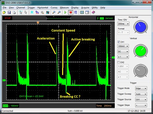
I had an arduino just move it between two positions (with no load) with about 1s of interval between them.
What we see here is the acceleration causing a high current spike (about 1A). As the speed increases the current levels off to a lower value.
When it is reaching the desired position we get a negative voltage spike which I assume is caused by passive breaking (the internal H-Bridge shorts out the motor pins).
Since there is no load some overshoot happens causing another spike as it goes into reverse to try and maintain the correct position.
Once the correct position is reached the current goes down to almost zero.
So the objective now is to measure the voltage drop with an Arduino.
The servo is moved in small angle increments , and when enough time as elapsed so that the servo has reached it's target position, if we verify that the current is not zero that means the servo is pushing against something so we do not make it move again.
Were are the results:
Not only does this give us some information regarding the grasping of objects but it should also prevent a lot of stripped gears.
Regards
As part of out 1m humanoid robot project we are developing several solutions to some common problems in robotics.
The fingers in the hand are supposed to be actuated by several servos.
Due to size and weight constraints we opted for analog servos.
This of course has limitations.
While we are going to use FSR's to sense if the fingers are grasping something it would be useful to get some measurement on the amount of torque each servo is putting out.
So first we added a small shunt resistor in line with the servo ground wire and used an oscilloscope to measure the voltage on that resistor (it's proportional to current).
I had an arduino just move it between two positions (with no load) with about 1s of interval between them.
What we see here is the acceleration causing a high current spike (about 1A). As the speed increases the current levels off to a lower value.
When it is reaching the desired position we get a negative voltage spike which I assume is caused by passive breaking (the internal H-Bridge shorts out the motor pins).
Since there is no load some overshoot happens causing another spike as it goes into reverse to try and maintain the correct position.
Once the correct position is reached the current goes down to almost zero.
So the objective now is to measure the voltage drop with an Arduino.
The servo is moved in small angle increments , and when enough time as elapsed so that the servo has reached it's target position, if we verify that the current is not zero that means the servo is pushing against something so we do not make it move again.
Were are the results:
phpBB [media]
Not only does this give us some information regarding the grasping of objects but it should also prevent a lot of stripped gears.
Regards

![]() by MarcoP
by MarcoP
Wed Jan 02, 2013 6:12 pm
Hi.
I am planning on powering the servos with an UBEC with enough juice to keep the voltage constant. However, just in case i will also monitor the voltage so i can compensate things in software.
Regarding different servos the idea is to calibrate them with know weights when assembled.
Rgds
I am planning on powering the servos with an UBEC with enough juice to keep the voltage constant. However, just in case i will also monitor the voltage so i can compensate things in software.
Regarding different servos the idea is to calibrate them with know weights when assembled.
Rgds
