Robotis based industrial type robot model.
Robotis based industrial type robot model.
![]() by sap1975
by sap1975
Sun Sep 20, 2009 10:51 am
Well. As a followup to the ”AX-12’s and RS-64’s on the same communications string” thread i figured i’d better share on the progress. (or lack of it)
The “funding” is coming together quite nicely and while i’m sorting that quite important bit i’ve been doing some designing and drawing. So far that’s all that’s been going on.
Anyways here it is. I’m planning on doing the actual build in a combination of resin casting, CNC milling and 3D prototype printing so the scale of the task ahead is a bit on the challenging side but i guess that’s what happens


Cheers
/Stig.

![]() by i-Bot
by i-Bot
Sun Sep 20, 2009 2:12 pm
I too am looking at converting my Robot arm for Dynamixel compatibility. My approach is different since I will convert my existing Mitsubishi arm and use custom servo controllers on existing motors and encoders.
When I compare your design with theirs I see some significant differences. The comparison may help you, though I do not know what application you have for your arm.
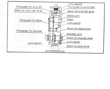
Here is my arm diagram:

You see the shoulder joint is direct above the waist joint. I guess this simplifies the kinematics and also provides better balance. The waist joint is very substantial and the waist motor is in the base.
The body contains the shoulder motor and some interface. It also has two springs to counter balance the shoulder and the elbow joints.
The chain shown in this diagram is how the elbow is counter balanced:
Your upper arm does not look very rigid, which may affect strength and accuracy.
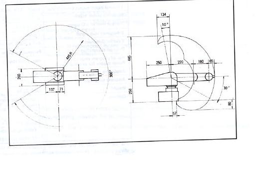
You see the wrist on my arm has both pitch and roll through a differential gear arrangement. This allows much more flexibility on hand orientation.
You may want to do a diagram like this to understand the arm capability and especially what constraints you have on hand orientation over the range:
I can maybe get some photos of any part of any interest to you, though it is rather difficult to get inside all parts.
![]() by sap1975
by sap1975
Sun Sep 20, 2009 5:00 pm
I didn’t think id find anyone else in this forum interested in the ”model” version of industrial robots.
That’s a Movemaster right? Have been having a look at those and they look quite interesting but are typically quite expensive.
Just for the info my design is heavily inspired by a Fanuc LR mate 200 series and is a 6 DOF solution. And yes i know that placing the motors etc. there will chew into the handling capabilities of the arm. I guess i forgot to include “photos” of the “wrist”
Payload fully extended is expected to be around ½ kilo. According to my limited math skills that is.
Ehh… how do you plan to go about the conversion?
I’m thinking closed loop servo controllers with RS485 interface. Not the easiest of projects.
Cheers
/Stig.
![]() by sap1975
by sap1975
Sat Feb 20, 2010 12:35 pm
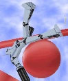
I’ve had the servos for a while now and i’ve finished the first conceptual mockup and learned quite a few things along the way.
This initial POC build is done by hand and is structurally weak hence the wobbling.
It’s currently running off a CM-5 and “programming” was done in Roboplus. I’m going to keep the CM-5 and build my own piece of software to run it in the future but first things first.
The first integration test was a success so i figured it was time to share. There are a few different components in here not initially designed to come together. AX-12’s, RX-64’s a standard servo and a force feedback sensor for the gripper. Basically the gripper when activated will start closing and do so until a preset amount of resistance is met and then stop holding that position.
Anyways. Here’s a video of how things are coming along.
Cheers
/Stig.
![]() by sap1975
by sap1975
Sat Feb 20, 2010 6:15 pm
Thank you very much
Well considering the list of potential problems with using a belt drive i was amazed of how well it worked out.
I did a lot of measuring and then just put it on there and it’s been working beautifully.
The joint however is snagging on the bracket in the extreme “up” position and that will cause it to slip. Ohh yea and i ground down the flat on the mounting pin thingie that connects the servo to the pulley so there’s a fair bit of backlash.
This will be sorted in the next version though. Also i don’t have any bearings in this setup so there are issues here and there but as i wrote it’s a mockup and it’s primary function is to figure out what works and what doesn’t.
Cheers
/Stig.
![]() by sap1975
by sap1975
Wed Jun 22, 2011 2:32 pm
The project has been dormant for a while but i’m actually just about to pick it up again.
It turned out to be a bit expensive doing the structural components and covers but I just put in an order for a 3d printer and that should allow me to move on.
I’ll update the thread once I get around to it
Cheers
/Stig.
![]() by limor
by limor
Wed Jun 22, 2011 5:41 pm
It is possible to reduce the shaking and vibrations of that nice arm by gradually slowing down the servos as they reach their target position. We developed an alternative firmware for AX12 that allows much better speed control so that you can create nice motion curve profiles to accelerate and decelerate as as you reach target positions.
check out http://actuated.wordpress.com
![]() by limor
by limor
Wed Jun 22, 2011 5:50 pm
![]() by sap1975
by sap1975
Wed Jun 22, 2011 6:03 pm
Once again to the rescue
Having said that... have you guys made custom firmware for the RX-64's as well?
The only reason i ask is that the two main servo's are RX-64's
And yes i would be happy to share the CAD files.
I have to re-work them first though since i did a bit of re-designing and have ordered and received the bearings that needs to go in there.
Btw. WOW... what an offer.
I hope i get the time to work on it a bit during the weekend.
I was planning on 3D printing the "shells" and CNC milling the "Arm" from aluminium which is one of the two main causes of shaking if that makes any sense. The other one by the way is the base. that should cure itself once it's a closed structure.
I'll get back to you.
And thanks again.
Cheers
/Stig.
![]() by i-Bot
by i-Bot
Fri Jun 24, 2011 2:21 pm
So the low level code should be very similar, though I never saw schematic of RX64 to check pinouts from processor. They do use an H bridge IC instead of the discrete FET used in AX, so there may be some rearrangement of the PWM outputs.
![]() by sap1975
by sap1975
Sat Jun 25, 2011 9:25 am
I have had a look at the model and i can tell that this is going to take some time to finish it since virtually all the mechanical parts needs to be drawn up. I have most of the in my head but it takes time to put them on "paper".
However there should be enough information in the stuff that's ready to see where i'm going and it would leave some playroom for ingenuity.
Limor: I would like to take you up on your offer on a joint venture sort of thing. Any help would be much appreciated and i'd be happy to send the current state to you. Just tell me if you'd prefer STP or STL and where to put it
Let me know what you'd prefer.
Cheers
/Stig.
![]() by sap1975
by sap1975
Wed Sep 07, 2011 4:07 pm
Getting the 3D printer has sped up things quite a lot. There where some initial teething problems with the printer but i'm just about getting things right now.
I have managed to get most of the structure designed and printed. i think there's about 30% - 35% left on mechanical. After that comes software.
Anyways. here's what it looks like now.
It's funny how all that work turned into something that looks a bit like a mechanical duck
Cheers
/Stig.

