<?xml version="1.0" encoding="UTF-8"?>
<feed xmlns="http://www.w3.org/2005/Atom" xml:lang="en-gb">
<link rel="self" type="application/atom+xml" href="http://forum.robosavvy.com/feed.php?f=15&amp;t=9127" />

<title>RoboSavvy Forum</title>
<subtitle>Robosavvy Forum: The largest online community of Humanoid Robot Builders</subtitle>
<link href="http://forum.robosavvy.com/index.php" />
<updated>2018-03-02T15:54:09+01:00</updated>

<author><name><![CDATA[RoboSavvy Forum]]></name></author>
<id>http://forum.robosavvy.com/feed.php?f=15&amp;t=9127</id>
<entry>
<author><name><![CDATA[Uwe]]></name></author>
<updated>2018-03-02T15:54:09+01:00</updated>
<published>2018-03-02T15:54:09+01:00</published>
<id>http://forum.robosavvy.com/viewtopic.php?t=9127&amp;p=43774#p43774</id>
<link href="http://forum.robosavvy.com/viewtopic.php?t=9127&amp;p=43774#p43774"/>
<title type="html"><![CDATA[Re: SAM-3 Servo teardown]]></title>

<content type="html" xml:base="http://forum.robosavvy.com/viewtopic.php?t=9127&amp;p=43774#p43774"><![CDATA[
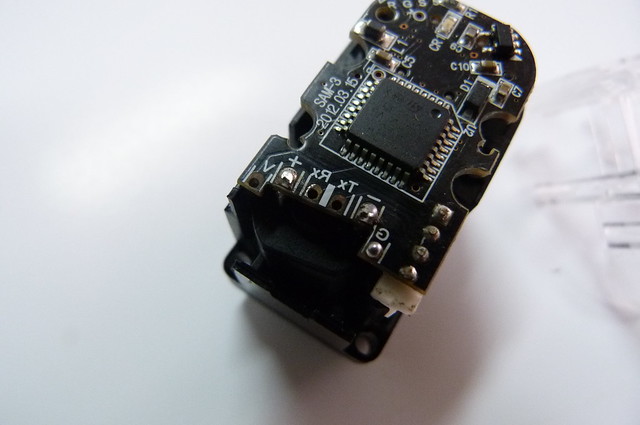
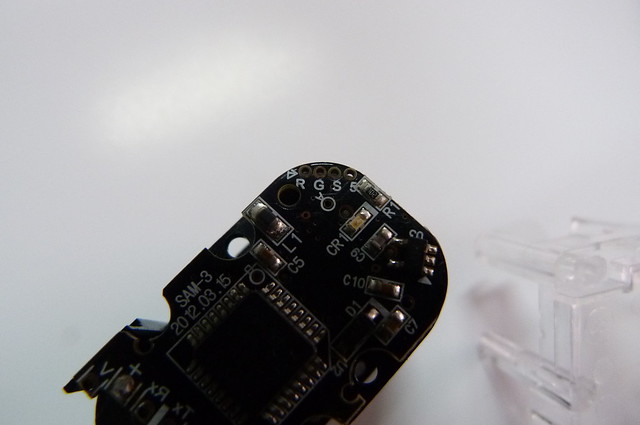
Hello Pedro,<br /><br />today i found the RoboSavvy Forum and your SAM-3 Servo teardown Post, 5 years to late. But I still answer your question regarding the RGS5:<br /><br />R stands for Reset and should be connected to Pin1, named NRST<br />G stands for Ground and should be connected to Pin4, named Vss<br />S stands for SWIM communication and should be connected to Pin 26, named PD1<br />5 stands for 5Volt and should be connected to Vdd<br /><br />The MPU is programmed with this 4 lines via a programming adapter like R-Link i.e.<br />You should test this statements with a multimeter, as this is only assumption. But I´m not surprised if you can confirm.<br /><br />Happy to have discovered this piece of internet,<br /><br />Uwe<p>Statistics: Posted by <a href="http://forum.robosavvy.com/memberlist.php?mode=viewprofile&amp;u=8293">Uwe</a> — Fri Mar 02, 2018 3:54 pm</p><hr />
]]></content>
</entry>
<entry>
<author><name><![CDATA[PedroR]]></name></author>
<updated>2013-03-06T16:26:03+01:00</updated>
<published>2013-03-06T16:26:03+01:00</published>
<id>http://forum.robosavvy.com/viewtopic.php?t=9127&amp;p=37325#p37325</id>
<link href="http://forum.robosavvy.com/viewtopic.php?t=9127&amp;p=37325#p37325"/>
<title type="html"><![CDATA[SAM-3 Servo teardown]]></title>

<content type="html" xml:base="http://forum.robosavvy.com/viewtopic.php?t=9127&amp;p=37325#p37325"><![CDATA[
Hi Nicolas<br /><br />Thank you for sharing that with us.<br /><br />I'm still quite curious as to what the &quot;R&quot;,&quot;G&quot;,&quot;S&quot; and &quot;5&quot;(?) pins are for.<br /><br />Anyway I wanted to point out something I believe I missed in my initial port:<br /><br />the SAM-3 servos come with a Horn that's compatible both with the Rivet system and also with the use of Screws.<br /><br />Bellow is a picture of the kit contents:<br /><img src="http://robosavvy.com/RoboSavvyPages/Robobuilder/SAM-HighTorqueServos/SAM3/SAM3_kitcontents.jpg" alt="Image" /><br /><br /><br />You'll notice the Horn has 4 large holes for rivets and 4 smaller ones where you can fit a nut and use a screw to attach them to other frame systems.<br /><br />This, combined with the possibility of adding a backhorn (shown in the first post) makes these servos very flexible in terms of use within the Robobuilder system and also outside the Robobuilder ecosystem.<br /><br /><br />A 4 pin molex to 4 pin molex cable is also included with the servos (this is the same cable that comes in 57xx robots as the connectors are exactly the same).<br /><br />Regards<br />Pedro.<p>Statistics: Posted by <a href="http://forum.robosavvy.com/memberlist.php?mode=viewprofile&amp;u=1061">PedroR</a> — Wed Mar 06, 2013 4:26 pm</p><hr />
]]></content>
</entry>
<entry>
<author><name><![CDATA[nicolas gomez]]></name></author>
<updated>2013-03-04T22:06:07+01:00</updated>
<published>2013-03-04T22:06:07+01:00</published>
<id>http://forum.robosavvy.com/viewtopic.php?t=9127&amp;p=37315#p37315</id>
<link href="http://forum.robosavvy.com/viewtopic.php?t=9127&amp;p=37315#p37315"/>
<title type="html"><![CDATA[Re: SAM-3 Servo teardown]]></title>

<content type="html" xml:base="http://forum.robosavvy.com/viewtopic.php?t=9127&amp;p=37315#p37315"><![CDATA[
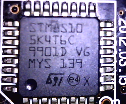
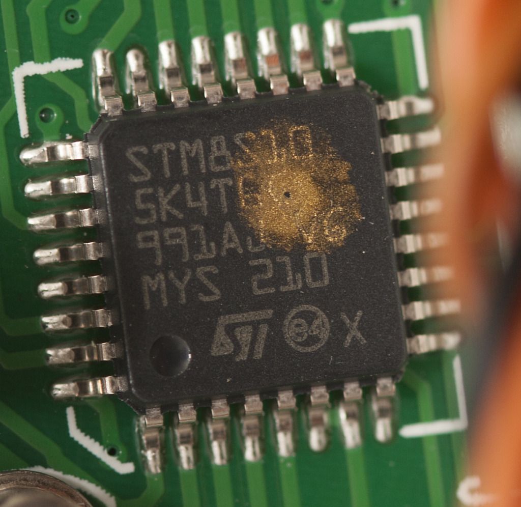
[quote=&quot;PedroR&quot;]<br /><br />STM processor (SM8S10, still 8 bit):<br /><br /><a href="http://www.flickr.com/photos/robosavvy/8528680964/" class="postlink"><img src="http://farm9.staticflickr.com/8112/8528680964_79f6dab604_o.png" alt="Image" /></a><br /><a href="http://www.flickr.com/photos/robosavvy/8528680964/" class="postlink">_SAM-3processor</a> by <a href="http://www.flickr.com/people/robosavvy/" class="postlink">RoboSavvy</a>, on Flickr<br />(if anyone has details or would like to clarify what this particular model is, you're most welcome <img src="http://forum.robosavvy.com/images/smilies/icon_smile.gif" alt=":)" title="Smile" /> as we couldn't find the datasheet )<br /><br /><br />Hiii !<br /><br />here more info about the microcontroller from the picture  the number part STM8S105K4 <br /><br />-Core 16 MHz advanced STM8 core with Harvard architecture and 3-stage pipeline Extended instruction set<br /><br />-Memories Medium-density Flash/EEPROM: Program memory up to 32 Kbytes Flash; data retention 20 years at 55 °C after 10 kcycles Data memory up to 1Kbytes true data EEPROM; endurance 300 kcycles RAM: Up to 2 Kbytes<br /><br />-Clock, reset and supply management 2.95 to 5.5 V operating voltage Flexible clock control, 4 master clock sources: Low power crystal resonator oscillator External clock input Internal,user-trimmable 16 MHz RC Internal low power 128 kHz RC Clock security system with clock monitor Power management: Low power modes (wait, active-halt, halt) Switch-off peripheral clocks individually Permanently active,low consumption power-on and power-down reset<br /><br />-Interrupt management Nested interrupt controller with 32 interrupts Up to 37 external interrupts on 6 vectors<br /><br />-Timers 2x16-bit general purpose timer, with 2+3 CAPCOM channels (IC, OC or PWM) Advanced control timer: 16-bit, 4 CAPCOM channels, 3 complementary outputs, dead-time insertion and flexible synchronization 8-bit basic timer with 8-bit prescaler Auto wakeup timer Window watchdog, independent watchdog timers<br /><br />-Communications interfaces UART with clock output for synchronous operation, Smartcard, IrDA, LIN master mode SPI interface up to 8 Mbit/s I2C interface up to 400 Kbit/s<br /><br />-Analog to digital converter (ADC) 10-bit, ±1 LSB ADC with up to 10 multiplexed channels, scan mode and analog watchdog<br /><br />-I/OsUp to 38 I/Os on a 48-pin package including 16 high sink outputs Highly robust I/O design, immune against current injection<br /><br /><img src="http://robosavvy.com/Builders/Niko2009/STM8S105xx.png" alt="Image" /><br /><br /><span style="font-weight: bold">DATASHEET</span><br /><!-- m --><a class="postlink" href="http://www.st.com/st-web-ui/static/active/en/resource/technical/document/datasheet/CD00200092.pdf">http://www.st.com/st-web-ui/static/acti ... 200092.pdf</a><!-- m --><br /><br />it is used in FlySky FS-GT3B Digital 3ch 2.4ghz TX &amp; RX LCD Transmitter &amp; Receiver<br />to  speed controler rc<br /><br /><!-- m --><a class="postlink" href="http://www.rccrawler.com/forum/electronics/321742-gt3b-hack-question-answer-thread-106.html">http://www.rccrawler.com/forum/electron ... d-106.html</a><!-- m --><br /><br /><img src="http://i1057.photobucket.com/albums/t390/atf300/gt3b.jpg" alt="Image" /><br /><br />hope this can help<br />Regards<p>Statistics: Posted by <a href="http://forum.robosavvy.com/memberlist.php?mode=viewprofile&amp;u=1610">nicolas gomez</a> — Mon Mar 04, 2013 10:06 pm</p><hr />
]]></content>
</entry>
<entry>
<author><name><![CDATA[PedroR]]></name></author>
<updated>2013-03-04T19:29:37+01:00</updated>
<published>2013-03-04T19:29:37+01:00</published>
<id>http://forum.robosavvy.com/viewtopic.php?t=9127&amp;p=37311#p37311</id>
<link href="http://forum.robosavvy.com/viewtopic.php?t=9127&amp;p=37311#p37311"/>
<title type="html"><![CDATA[SAM-3 Servo teardown]]></title>

<content type="html" xml:base="http://forum.robosavvy.com/viewtopic.php?t=9127&amp;p=37311#p37311"><![CDATA[
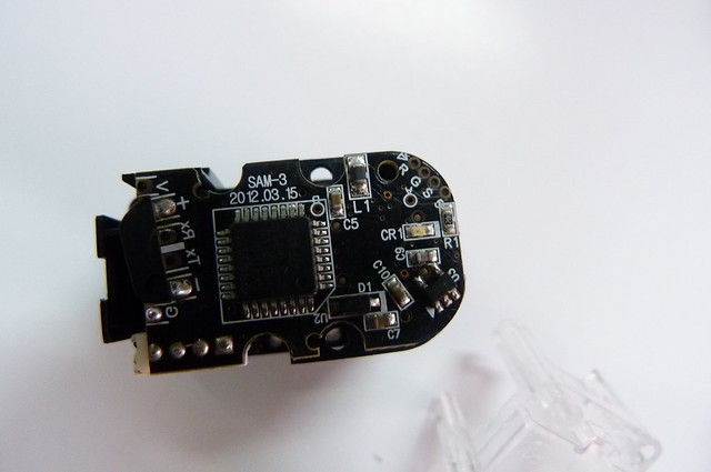
Hi all<br /><br />As we get clear of the Christmas aftershock (yay!) we're back to our business of tearing down and hacking the newest products.<br /><br />We now have the SAM-3 servo (the core of RQ-HUNO) for sale in our store (see here <!-- m --><a class="postlink" href="http://robosavvy.com/store/SAM-3">http://robosavvy.com/store/SAM-3</a><!-- m --> ).<br />This servo uses the same Daisy Chain technology and exactly the same protocol used by the wCk servos (the ones on the 5710/5720), meaning they can be connected to your 57xx robot.<br /><br />The main advantage of the SAM-3 is its smaller size. It also combines a bit of the black and transparent servos and - as we found - exposes some veyr neat features under the casing.<br /><br /><a href="http://www.flickr.com/photos/robosavvy/8528991330/" class="postlink"><img src="http://farm9.staticflickr.com/8380/8528991330_8cdecf0078_z.jpg" alt="Image" /></a><br /><a href="http://www.flickr.com/photos/robosavvy/8528991330/" class="postlink">SAM3_frontback</a> by <a href="http://www.flickr.com/people/robosavvy/" class="postlink">RoboSavvy</a>, on Flickr<br /><br /><a href="http://www.flickr.com/photos/robosavvy/8527567797/" class="postlink"><img src="http://farm9.staticflickr.com/8230/8527567797_f22f6145d4_z.jpg" alt="Image" /></a><br /><a href="http://www.flickr.com/photos/robosavvy/8527567797/" class="postlink">_P1040003</a> by <a href="http://www.flickr.com/people/robosavvy/" class="postlink">RoboSavvy</a>, on Flickr<br /><br />Taking the cover off we see the gearset. Interestingly Robobuilder chose to use 1 metal gear not on the main output shaft but the gear just before that.<br />This is a 4 gear reduction much like the wCKs.<br />FYI there's a 5kgf.cm version (SAM-5) with the exact same form factor, just different gear reduction.<br /><br />Also notice the connector. it's the same used by wCk modules but there's only one on SAM 3 servos (however we have found solder pads for a second one in the pcb on the other side; see bellow).<br /><br /><br /><a href="http://www.flickr.com/photos/robosavvy/8527567215/" class="postlink"><img src="http://farm9.staticflickr.com/8513/8527567215_320993c8f4_z.jpg" alt="Image" /></a><br /><a href="http://www.flickr.com/photos/robosavvy/8527567215/" class="postlink">_P1040013</a> by <a href="http://www.flickr.com/people/robosavvy/" class="postlink">RoboSavvy</a>, on Flickr<br /><br />Taking the transparent cover off (on the other side) it reveals a number of unpopulated solder pads and - surprisingly - not an ATMEGA8 processor but an STM processor (SM8S10, still 8 bit):<br /><br /><a href="http://www.flickr.com/photos/robosavvy/8528680964/" class="postlink"><img src="http://farm9.staticflickr.com/8112/8528680964_79f6dab604_o.png" alt="Image" /></a><br /><a href="http://www.flickr.com/photos/robosavvy/8528680964/" class="postlink">_SAM-3processor</a> by <a href="http://www.flickr.com/people/robosavvy/" class="postlink">RoboSavvy</a>, on Flickr<br />(if anyone has details or would like to clarify what this particular model is, you're most welcome <img src="http://forum.robosavvy.com/images/smilies/icon_smile.gif" alt=":)" title="Smile" /> as we couldn't find the datasheet )<br /><br /><br />Back to the solder pads, we haven't tested all of them but from the silk screen (some) are easy to figure out:<br /><a href="http://www.flickr.com/photos/robosavvy/8528681208/" class="postlink"><img src="http://farm9.staticflickr.com/8391/8528681208_816dc808d0_z.jpg" alt="Image" /></a><br /><a href="http://www.flickr.com/photos/robosavvy/8528681208/" class="postlink">_P1040016</a> by <a href="http://www.flickr.com/people/robosavvy/" class="postlink">RoboSavvy</a>, on Flickr<br /><br />Here we get access to the second connector for the serial port to build the daisy chain.<br />Since these servos have only 1 external connector there are only 2 ways to build the daisy chain: either build the cable (by connecting multiple RX and TX in parallel or in a W cable as we get in RQ-HUNO) or otherwise use the solder pads here.<br /><br /><br /><a href="http://www.flickr.com/photos/robosavvy/8528681510/" class="postlink"><img src="http://farm9.staticflickr.com/8377/8528681510_56a025d073_z.jpg" alt="Image" /></a><br /><a href="http://www.flickr.com/photos/robosavvy/8528681510/" class="postlink">_P1040015</a> by <a href="http://www.flickr.com/people/robosavvy/" class="postlink">RoboSavvy</a>, on Flickr<br /><br />Then there are these mystery solder pads. It's not clear what these are but we suspect they are DIOs for the servo (the wCks also have them). [ again any and all suggestions welcome <img src="http://forum.robosavvy.com/images/smilies/icon_smile.gif" alt=":)" title="Smile" /> ]<br />CR1 is a Blue LED that is included in all SAM-3 servos. It is addressable by using the serial protocol to set the DIO port to 0 or 1. (the original wck protocol gives you access to 2 DIOs and 1 analog in if I'm not mistaken)<br />I remind you the serial protocol is exactly the same as the one for wCK modules and can be found here (the part that applies to SAM-3 is from page 20 onwards): <!-- m --><a class="postlink" href="http://robosavvy.com/RoboSavvyPages/Robobuilder/robobuilder-creator-users-manual.pdf">http://robosavvy.com/RoboSavvyPages/Rob ... manual.pdf</a><!-- m --><br /><br /><br /><a href="http://www.flickr.com/photos/robosavvy/8528680806/" class="postlink"><img src="http://farm9.staticflickr.com/8237/8528680806_c94e18988f_z.jpg" alt="Image" /></a><br /><a href="http://www.flickr.com/photos/robosavvy/8528680806/" class="postlink">_P1040017</a> by <a href="http://www.flickr.com/people/robosavvy/" class="postlink">RoboSavvy</a>, on Flickr<br />The casing is also carefully thought out with a small hole in the back for cables to exit. The hole is actually very close to the solder points of RX and TX.<br /><br /><br /><a href="http://www.flickr.com/photos/robosavvy/8527877859/" class="postlink"><img src="http://farm9.staticflickr.com/8389/8527877859_9778278c2c_c.jpg" alt="Image" /></a><br /><a href="http://www.flickr.com/photos/robosavvy/8527877859/" class="postlink">SAM3-backhorn</a> by <a href="http://www.flickr.com/people/robosavvy/" class="postlink">RoboSavvy</a>, on Flickr<br /><br />One other very neat feature in the casing design is a placeholder for a nut on the opposite side of the horn (for the backhorn). This should make it easier to build systems where you don't want to use the joint system and/or need to attach a proper backhorn.<br /><br />As far as I recall this was not possible on wCk modules and is a feature on these smaller servos.<br /><br /><br />The 3 kgf.cm torque is not mind blowing but the rich serial protocol makes this a very appealing servo. The mystery solder pads may well reserve some other interesting features as well.<br />Also bear in mind the servo can operate in continuous rotation (wheel mode) with built in speed control in addition to position control mode and has a very discrete form factor.<br /><br />One application I can immediately think of are Pan &amp; Tilt systems for the 5710/5720 robots. <br /><br />Robobuilder has posted some sample code for interfacing the servo to an Arduino here <!-- m --><a class="postlink" href="http://rqhuno.blogspot.pt/search/label/With%20Arduino">http://rqhuno.blogspot.pt/search/label/With%20Arduino</a><!-- m --><br /><br /><br />If anyone has the motivation to take one and test it to find out what the solder pads do and test the wCk protocol extensively on these servos, email us ( support at robosavvy dot com ) and we'll be happy to give away one servo in exchange for documenting all these hidden features or creative uses in our forum.<br /><br />Kind Regards<br />Pedro<p>Statistics: Posted by <a href="http://forum.robosavvy.com/memberlist.php?mode=viewprofile&amp;u=1061">PedroR</a> — Mon Mar 04, 2013 7:29 pm</p><hr />
]]></content>
</entry>
</feed>