Any interest in designing some custom RoboBuilder brackets?
Any interest in designing some custom RoboBuilder brackets?
![]() by Joe
by Joe
Wed Oct 26, 2011 4:25 am
I'm starting to look seriously into designing some custom brackets for RoboBuilder servos — mainly with the intent to implement parallel linkage legs. But some of these will be general-purpose, for example, a bracket that wraps around an RB servo and provides an idler bearing opposite the servo horn.
My basic plan is to draw these out, probably in OmniGraffle (though I could be talked into using QCad instead), and have them cut out of aluminum at a laser or waterjet shop. Then, most likely, bend them myself (which I understand is not too hard if you have a decent metal brake, which I also understand is not too expensive).
So. Before I go off and do this all myself, is there anyone interested in collaborating on such things?
Thanks,
- Joe

![]() by Joe
by Joe
Wed Oct 26, 2011 7:58 pm
I'm certainly willing to have a try at it that way... but I think the brackets will need to be pretty thin to attach to the sides of the servo; those long bolts that come from RB are barely longer than the servo itself. So that doesn't allow for much thickness, unless we find a source for even longer bolts.
So that's why I've been assuming aluminum. Also I worry about whether 3D printed brackets would be strong enough for load-bearing members. But we can certainly try.
So that's why I've been assuming aluminum. Also I worry about whether 3D printed brackets would be strong enough for load-bearing members. But we can certainly try.
![]() by i-Bot
by i-Bot
Wed Oct 26, 2011 8:20 pm
Because the of the unique access to the middle of the output shaft, the need to have a thickness of material on both sides of the servo is often removed. The standard screws will just manage 2 thickness of 1/16 th material (aluminium or carbon fibre).
I also use hex material threaded 2mm as spacers.
Look at how the metal brackets are attached and follow that.
I like the metal brackets and the metal servo output disks, but the metal joints are no stronger than the plastic.
The slots in the and of the wCk are also very useful, I built a backbone of 4mm aluminium where the hip, arm and head pan servos simply slot on.
Last edited by i-Bot on Thu Oct 27, 2011 1:43 pm, edited 1 time in total.
![]() by Joe
by Joe
Thu Oct 27, 2011 12:28 am
i-Bot wrote:Because the of the unique access to the middle of the output shaft, the need to have a thickness of material on both sides of the servo is often removed. The standard screws will just manage 1 thickness of 1/16 th material (aluminium or carbon fibre).
Yeah, I thought hard about how to use that middle output... but for the leg mechanism, I just don't see it. I want struts on both sides of the leg (inseam and outside) for stability, which implies powering one, and idling the other.
I guess I could just attach the servos on one side, but that seems weaker (and probably floppier) than it needs to be. It looks to me like I could, just barely, get the screws through material on both sides. Tonight I'll try it with some extra brackets and see what happens.
I also use hex material threaded 2mm as spacers.
I can't quite picture what you mean here. Can you post a photo or product link?
The slots in the and of the wCk are also very useful, I built a backbone of 4mm aluminium where the hip, arm and head pan servos simply slot on.
Agreed. I think your point is a good one: there are many ways to attach to a wCK servo besides the usual mounting-screws-and-servo-horn. Sometimes the traditional approach may be best, but I'll look for opportunities to take advantage of the other ways.
Thanks,
- Joe
![]() by i-Bot
by i-Bot
Thu Oct 27, 2011 2:05 pm
Sorry, I meant to say that the screws are just long enough for 2 thickness if Aluminium, corrected above.
You see the metal brackets kit uses two thickness here:
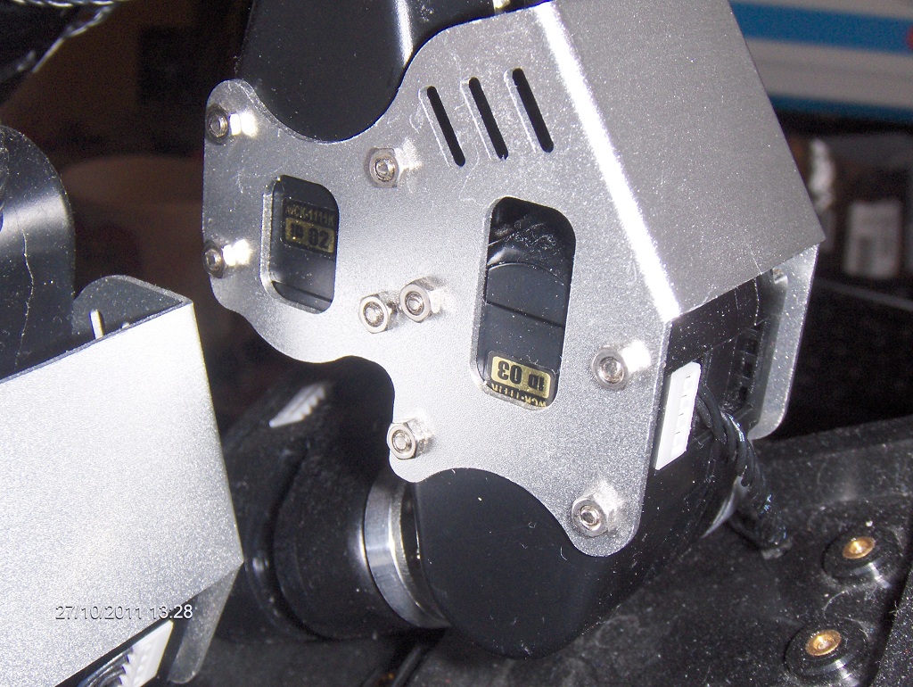
Homemade brackets also work

I used the hex spacers below when using carbon fibre:
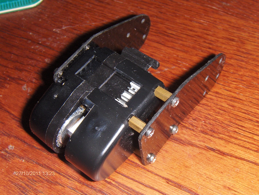
The spacers offset the mount to the height of the servo disk. Also not shown here, but you also need washers if you use carbon fibre. They are not installed in this pic and you see the danger of damaging the carbon fibre because the far side screw head is not well supported on the servo side.
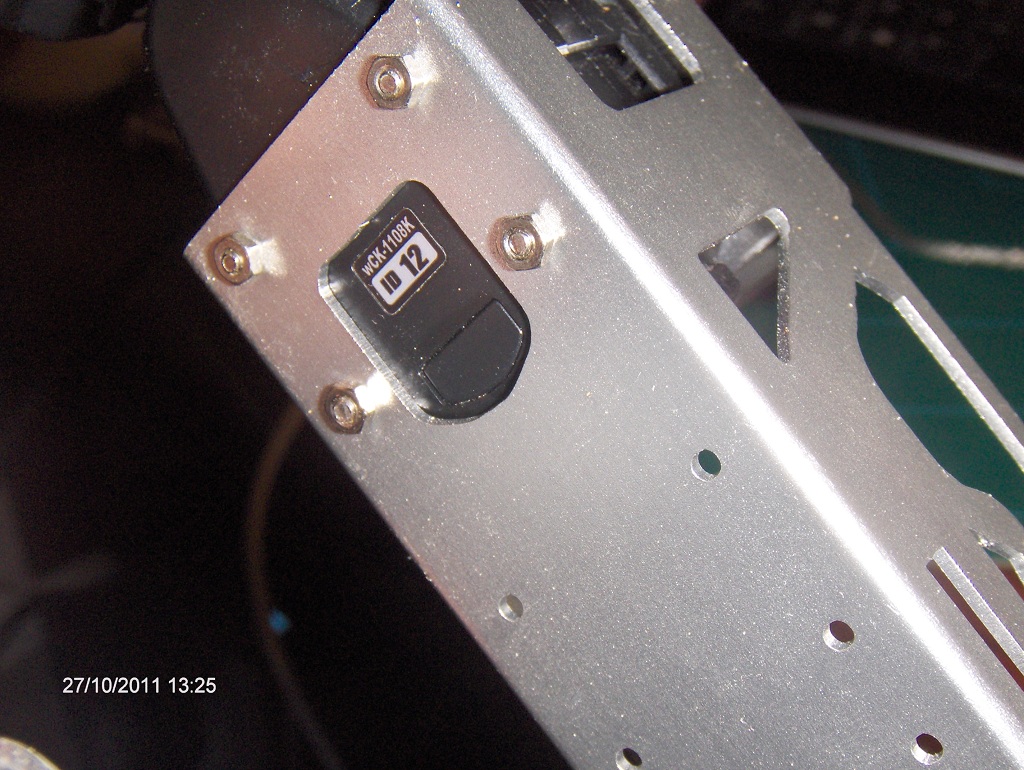
Also a pic of the 4mm backbone:

This gives plenty of mounting space for non RBC electronics, including space for a good sized LiPo battery.

You see the metal brackets kit uses two thickness here:
Homemade brackets also work
I used the hex spacers below when using carbon fibre:
The spacers offset the mount to the height of the servo disk. Also not shown here, but you also need washers if you use carbon fibre. They are not installed in this pic and you see the danger of damaging the carbon fibre because the far side screw head is not well supported on the servo side.
Also a pic of the 4mm backbone:
This gives plenty of mounting space for non RBC electronics, including space for a good sized LiPo battery.
![]() by Joe
by Joe
Thu Oct 27, 2011 3:06 pm
Beautiful work, i-Bot! I'm encouraged. And now I see what you mean about the spacer — I was thinking I would need something like that, but using hex spacers that fit into the indentation in the servo is brilliant. (You wouldn't happen to have a supplier/part-number for those, would you? ...And for the longer screws that fit so perfectly when you use them?)
Thanks for the pictures. I made good progress last night on bracket designs for the parallel linkage legs. In 2D, it all looks good; next I need to work out the details in 3D. I'll post pictures of my own once I have more to show.
Best,
- Joe
Thanks for the pictures. I made good progress last night on bracket designs for the parallel linkage legs. In 2D, it all looks good; next I need to work out the details in 3D. I'll post pictures of my own once I have more to show.
Best,
- Joe
![]() by i-Bot
by i-Bot
Thu Oct 27, 2011 3:28 pm
Sorry, I could not find a supplier. I made my own from 5/32 inch AF hex brass rod. They are drilled and tapped M2. This means that two screws are used into the spacer. The short one is the standard small M2 screw, the longer one is the standard long screw( though I even had to shorten some slightly !)
I used 5/32 brass because I had some. You could use 4mm AF and any material.
I used 5/32 brass because I had some. You could use 4mm AF and any material.
Last edited by i-Bot on Thu Oct 27, 2011 3:56 pm, edited 1 time in total.
![]() by i-Bot
by i-Bot
Thu Oct 27, 2011 3:52 pm
You might also want to consider making the joint layout similar to Darwin for the legs. Of course your parallel linkage would need to be added, but having the spherical hip and the common ankle axis, makes the kinematics easier.
http://robosavvy.com/site/index.php?option=com_content&task=view&id=221&Itemid=2
This also shows the angle ranges I get on my Robobuilder
http://robosavvy.com/site/index.php?option=com_content&task=view&id=221&Itemid=2
This also shows the angle ranges I get on my Robobuilder
![]() by Joe
by Joe
Fri Oct 28, 2011 3:23 pm
Thanks again, i-Bot. Your presence here is a real benefit to the hobby.
I was able to find M2 threaded rod from McMaster, as well as M2 hex standoffs. But I'm not pleased with how the brackets are coming together. The need for the brackets to provide an idler bearing opposite the servo horn, plus the M2x40 mounting screw problem, makes everything much harder than it seems like it should be. It can certainly be done, using standoffs and some creative bracket geometry, but it's starting to feel a little Rube Goldbergish.
I'm thinking about backing up and trying an approach where I enclose a pair of wCK servos in a box, building up joints that way, as in OmniZero 2:

The boxes could be 3D printed, and could either have mounting posts that attach to the wCK's end attacher thingy, or could simply enclose them tightly. Either way, the mounting-screws problem would be eliminated, and the box would also provide the idler bearings.
On the other hand, the more I look at the Uptech servos, the more I like them. They have either an idler bearing or a double-ended output shaft (not sure which, but I've got one on the way so I'll find out soon!). They have sophisticated firmware with things like overcurrent/overtemp protection. They might fit standard servo brackets, but even if they don't, it looks pretty easy to design your own, as there are no ridiculously long mounting shafts to deal with. And they seem surprisingly well documented and supported — a brief search turns up detailed manuals and data sheets, including the Molex part number of the cable connector!
So, I'm going to see what I can do with those as well. Trying to use wCK servos in the way I want (e.g. for parallel linkage legs) feels like a round-peg-in-a-square-hole situation. But time will tell!
Best,
- Joe
I was able to find M2 threaded rod from McMaster, as well as M2 hex standoffs. But I'm not pleased with how the brackets are coming together. The need for the brackets to provide an idler bearing opposite the servo horn, plus the M2x40 mounting screw problem, makes everything much harder than it seems like it should be. It can certainly be done, using standoffs and some creative bracket geometry, but it's starting to feel a little Rube Goldbergish.
I'm thinking about backing up and trying an approach where I enclose a pair of wCK servos in a box, building up joints that way, as in OmniZero 2:
The boxes could be 3D printed, and could either have mounting posts that attach to the wCK's end attacher thingy, or could simply enclose them tightly. Either way, the mounting-screws problem would be eliminated, and the box would also provide the idler bearings.
On the other hand, the more I look at the Uptech servos, the more I like them. They have either an idler bearing or a double-ended output shaft (not sure which, but I've got one on the way so I'll find out soon!). They have sophisticated firmware with things like overcurrent/overtemp protection. They might fit standard servo brackets, but even if they don't, it looks pretty easy to design your own, as there are no ridiculously long mounting shafts to deal with. And they seem surprisingly well documented and supported — a brief search turns up detailed manuals and data sheets, including the Molex part number of the cable connector!
So, I'm going to see what I can do with those as well. Trying to use wCK servos in the way I want (e.g. for parallel linkage legs) feels like a round-peg-in-a-square-hole situation. But time will tell!
Best,
- Joe