RN1- 3024 Diagram's for Add-Ons - Please STICKY!
RN1- 3024 Diagram's for Add-Ons - Please STICKY!
![]() by Morbeious
by Morbeious
Sun Apr 09, 2006 4:46 pm
Eh, Gang
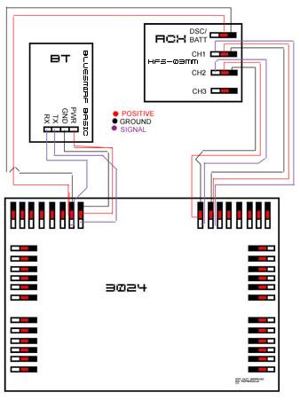
I made the following graphic for newbies.. and alike.. when discussing the connection points on the 3024 for different addon's if people could draw the lines on the diagram, this should make it alot easier for people to read, mainly cause the back of the RN-1 in pictures is so full of wires..

I made the following graphic for newbies.. and alike.. when discussing the connection points on the 3024 for different addon's if people could draw the lines on the diagram, this should make it alot easier for people to read, mainly cause the back of the RN-1 in pictures is so full of wires..
Last edited by Morbeious on Tue Apr 11, 2006 12:23 am, edited 2 times in total.
Robots Own/Operated: HeathKit Jr, OmniBot 2000, Lego MindStorms, RSV2, RoboNova-1


![]() by robodude666
by robodude666
Sat Jun 17, 2006 1:11 pm
WOW MAN! This is an awesome idea! I am planning on getting a RoboNova (as soon as I hit 1000$) and I was looking at sensors I can plug into the baby. I didn't understand how the connections should be like for BlueTooth for example. But now I do!
So the black is ground, red is power and white is TX (or is it RX since TX is being plugged into it?), and also black is for RX (or TX since RX is being plugged into it.)
Also, what is this gyro I keep reading about? And the RCX is the lego mindstorm's RCX? :s I looked up the model that is on the pic and I get
ttp://www.robotstore.com/store/product. ... catid=1546 so im guessing its not the lego mindstorm's RCX and some sort of receiver for erm, receiving stuff.
![]() by Gman
by Gman
Sat Jul 01, 2006 2:47 am
Hello everyone
I added a 2-axis accelerometer to my robonova to enable the robot_tilt: routine.
this is the accelerometer
http://www.dimensionengineering.com/DE-ACCM2G.htm
I soldered an old cd audio cable to a 14 pin ic socket
made sure the wires were going to the proper pins
(ground at the outer edge, signal at the inward pin and +voltage in the middle)
I am only using the x axis right now. y axis output is not connected on my robot.
here is the diagram showing X AND Y axis connected and ready to use
http://robosavvy.com/Builders/Gman/dime ... ometer.jpg
I put the accelerometer into the socket and it fits nicely inside the head behind the LED.
It's held in place with some double sided foam tape
Here is a picture of the results
http://robosavvy.com/Builders/Gman/acce ... 0setup.jpg
This sensor is very sensitive and I had to change the robot_tilt: values
I messed around until finding that this works for me
IF A < 95 THEN GOTO tilt_low
IF A > 160 THEN GOTO tilt_high
![]() by MacPro7GB
by MacPro7GB
Thu May 31, 2007 12:26 am
Gman wrote:Hello everyone
I added a 2-axis accelerometer to my robonova to enable the robot_tilt: routine.
this is the accelerometer
http://www.dimensionengineering.com/DE-ACCM2G.htm
I soldered an old cd audio cable to a 14 pin ic socket
made sure the wires were going to the proper pins
(ground at the outer edge, signal at the inward pin and +voltage in the middle)
I am only using the x axis right now. y axis output is not connected on my robot.
here is the diagram showing X AND Y axis connected and ready to use
http://robosavvy.com/Builders/Gman/dime ... ometer.jpg
I put the accelerometer into the socket and it fits nicely inside the head behind the LED.
It's held in place with some double sided foam tape
Here is a picture of the results
http://robosavvy.com/Builders/Gman/acce ... 0setup.jpg
This sensor is very sensitive and I had to change the robot_tilt: values
I messed around until finding that this works for me
IF A <95> 160 THEN GOTO tilt_high
So if I am adding an accelerometer, a blue tooth module, and 2 gyros where do I connect everything to? Is there a single diagram showing 2 GWS PG-03 gyros, a bluesmirf module, and a sparkfun ADXL320 accelerometer.
![]() by MacPro7GB
by MacPro7GB
Mon Jun 04, 2007 8:54 pm
I got both of my gyros working but I am having a problem with my accelerometer and bluetooth. I can link the bluesmirf module with my PC but I cannot get it to communicate with the robot. I also do not seem to be able to get the accelerometer working.
I am pretty sure it is in my code. I have the BT hooked up as shown in the diagram above. I have my gyros on AD 0 & 4 for one and AD 1 & 5 for the other one. Both are working good. I have my accelerometer hooked up to AD 3 for power and x axis and to AD 2 for the y axis. Can someone take a look at my code and see what I do not have set right?
http://robosavvy.com/Builders/MacPro7GB/test.txt
![]() by limor
by limor
Tue Jun 05, 2007 12:03 am
MacPro7GB wrote:I can link the bluesmirf module with my PC but I cannot get it to communicate with the robot.
Bluesmirf is set to communicate with Rx/Tx at 9600bps by default. You may need to issue the right ATSW20... command to change the baud rate. see Bluesmirf documentation.
![]() by Pev
by Pev
Tue Jun 05, 2007 7:22 am
MacPro7GB wrote:I can link the bluesmirf module with my PC but I cannot get it to communicate with the robot.
Had a quick look at thge code and the TX is set to 9600 so I think that is probably okay. The ETX and ERX labelling on the MR-C3024 can be a bit confussing with you needing to connect the Bluesmirf TX to ETX and Bluesmirf RX to ERX I think - anyway it was the opposite way round to the way I thought so you may want to try swapping the TX and RX lines
Pev
