New open-source controller
![]() by Voelker
by Voelker
Mon Jun 02, 2008 5:14 pm
The board i'am currently designing is not intend to be use only in the robonova, but as the controller is a limitation of this robot more people may be interesteed in having another "open" controller. We are not all living in Japan, so we must build what can't come to us.

![]() by limor
by limor
Thu Jun 05, 2008 2:26 pm
StuartL wrote:Ok, I have a fair degree of experience in digital electronics and am not averse to the idea of making a new generic controller for humanoid robots. I don't think it's a disaster to implement on-board gyros, accelerometers, bus interfaces and potentially some servo outputs. I'm not sure of the constraints of the RN PCB cavity but I'm willing to assist in the design, programming etc.
I also think it'd be trivial to make daughter-boards for controlling batches of servos.
I think the ideal board would be a small very cheap atmega128 board sold retail at 20$ with the following features:
a) a bus connecting multiple boards over the one of the 2 high speed serial UARTs.
b) Each such board would support only 8 servos in order for it to be as small as possible and also in order to be able to perform current measurement on the output current to the servos (in order to measure EMF and potentially get position and speed estimation for servos that dont have a serial protocol).
c) through-hole connections to most of the atmega128 pins
d) No on-board gyros or anything to make the board expensive. It is cheaper to just buy one of the many sparkfun analog or I2C sensor boards. (see robosavvy.com/store)
![]() by limor
by limor
Thu Jun 05, 2008 2:44 pm
http://robosavvy.com/store/product_info.php/products_id/434

![]() by Voelker
by Voelker
Thu Jun 05, 2008 3:34 pm
I have finally finished the schematic of my board :
-PIC32
-programmable over USB
-30 servos outputs
-7 ADC channel
-3 pwm output
-3 input capture ports
-2 serial channel
-1 I2C
-1 SPI + IO (to connect a sd card adapter)
-3 external interrupts
-1 reset switch
![]() by limor
by limor
Thu Jun 05, 2008 4:08 pm
Voelker wrote:This board is very interesting, but with 8 servos output it doesn't seem adapted to humanoid. Using mutliple board all managing only 8 servos is a good idea, but for small robots the size is a main concern ...
I agree that the board mentioned above may not be small enough to place multiple units inside the Robonova chest. But i think that if you are designing a board that is supposed to attract a large enough following, it needs to be really small and really cheap.
Voelker wrote:I have finally finished the schematic of my board :
-PIC32
-programmable over USB
-30 servos outputs
-7 ADC channel
-3 pwm output
-3 input capture ports
-2 serial channel
-1 I2C
-1 SPI + IO (to connect a sd card adapter)
-3 external interrupts
-1 reset switch
[/quote]
I'm not familiar with PIC in general but this sounds like very good specs.
30 servos and 3 pwm ? why this separation ?
![]() by i-Bot
by i-Bot
Thu Jun 05, 2008 6:05 pm
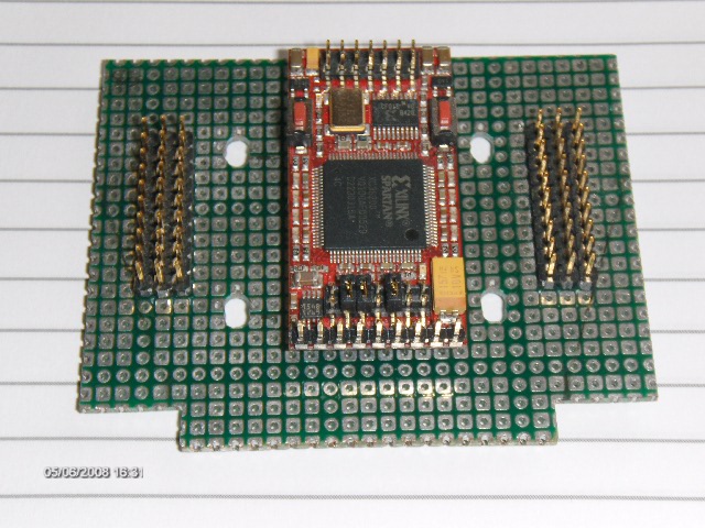
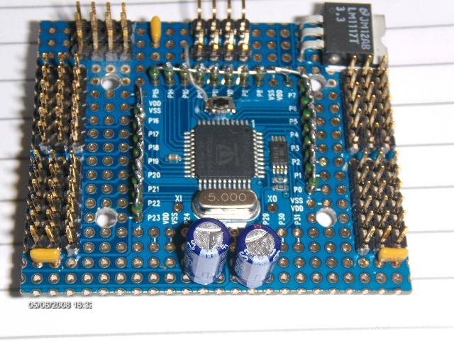
Here are couple of examples:
This is a Xilinx Spartan controller with 20 uarts or 20 PWM and 2 picoblaze processors. The board is bigger than standard, but the back still just fits.
This a Parallax Propeller controller. either 24 UARTS or 24 PWM, 2 high speed serial and 2 I2C ports. based on parallax protoboard.
So what am I using now, well actually back with the C3024, based on what I learnt, I have a new firmware which meets my needs without a controller swap. The controller is fine for the servos. I have a high speed interrupt driven serial port, so it works as a slave to another processor or PC.
![]() by Voelker
by Voelker
Thu Jun 05, 2008 7:16 pm
My board is gonna have the same form factor as the robonova one, so no problem to swap the board.
The pwm output on my board are intend to be use to controll motor.
![]() by i-Bot
by i-Bot
Thu Jun 05, 2008 7:52 pm
The servos need an open collector pullup if you want to read position or use HMI. The ATMega provides this as an internal configurable current source. I think you will need them on the PIC32.
The propeller is 3.3V and not 5V tolerant, so I pull up the pins to 3.3 V and this seems enough. With the PIC32 you could pull up to 5V if you want.
I dumped the PWM since it was not used. Also dumped:
The IR remote because PS2 is better
PWM gyros in favour of I2C IMU
Music, too much CPU
Sonar, use I2C
RC, use PS2
![]() by i-Bot
by i-Bot
Sat Jun 07, 2008 10:01 am
From your spec you say 30 servo outputs. You can use the Hitec and many other servos in output only mode, but most robotic servos need bidirectional control. This is either pulse or serial and is true of the Hitec and KHR in robot applications.
http://robosavvy.com/Builders/i-Bot/HSR ... 0Servo.pdf
The bidirectional requirement determines the need for pullups, but also is a major design factor for both the hardware and software.
When just outputting to a servo then use of timers and interrupts is OK if you are careful on design. If you use a serial protocol such as serial HMI, again the timing is tight, but predictable.
When you have to measure incoming pulses to microsec accuracy, it becomes more of a challenge. You need to check the pin at least every microsec, which is more difficult for interrupt. If you do it by software loop you have about 2 millisec of time where you must disable interrupts.
You should explore the pin change detect of the PIC for both the pullups and the input interrupt. The pins with these feature seem to conflict with other peripherals. Also you should check interrupt timing and latency to see if an interrupt is fast enough.
This is why I chose the Propeller and the FPGA. With the prop, I dedicate a cog to the servos, so can do sw timing without affecting other cogs. The fpga has 20 seperate bidirectional PWM controllers and two processors.
On my Atmega PWM software, I simply don't read the servos. I use the standard software and standard moves to create poses and motions. Then execute them within the new codein either standard or modified form. Serial HMI allows read though.
![]() by Voelker
by Voelker
Wed Jul 02, 2008 9:52 am
A first daughter board with a large prototyping area will be available in order to allow connection of other modules.