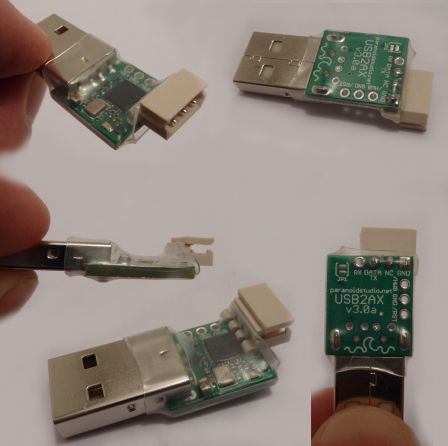
USB2AX, a small powerful USB to Dynamixel controller
Hi xevel
I was looking at the PCBs and the markings on it and got a bit confused about where the 3 pin AX connector goes.
- Can you post a picture with a 3pin servo connector on the board to get a better idea of the size and how it all connects and comes together?
- One more question: in your early prototypes you were using the PCB as a USB connector (ie you would insert the pcb inside the USB port).
I see on these batches that you'se used a propper USB plug.
Is there any particular reason for this?
Given that the great advantage of your project is really the small size, the full USB plug looks a bit bulky (at least in the pics maybe when we hold it it still looks very small.)
Thanks
Pedro
I was looking at the PCBs and the markings on it and got a bit confused about where the 3 pin AX connector goes.
- Can you post a picture with a 3pin servo connector on the board to get a better idea of the size and how it all connects and comes together?
- One more question: in your early prototypes you were using the PCB as a USB connector (ie you would insert the pcb inside the USB port).
I see on these batches that you'se used a propper USB plug.
Is there any particular reason for this?
Given that the great advantage of your project is really the small size, the full USB plug looks a bit bulky (at least in the pics
Thanks
Pedro
Hi Pedro, and sorry for the delay, I spent a few days resting (I'm better now  )
)
- The silkscreen on the bottom indicates GND, N/C (Not Connected to the circuit of the USB2AX) and Data. These are the pins where the Dynamixel connector will be soldered, as seen in this pictures:
(click for larger size)
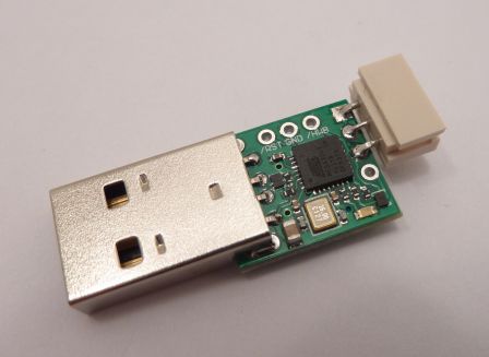
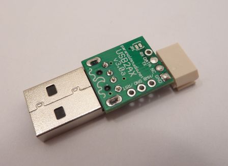
The connector used here is a straight connector of which I bent the leads, but next time I'll try a real right-angled one instead.
In smaller font are indicated TX and RX, as well as the jumper JP1. These are of concern only if one would want to use the USB2AX as an USB to Full-duplex TTL Serial converter (the "normal" serial port with logic levels between 0 and 5v). If you use the USB2AX to talk with Dynamixels, then you don't need bother with these at all.
JP1 is a solderable jumper that connects DATA/TX to RX.
* To use the USB2AX to talk with Dynamixels, DATA/TX and RX have to be connected, and this is the default state.
* To use the USB2AX as a USB to TTL Serial adapter DATA/TX and RX have to be disconnected by cutting the thin trace between the two pads of JP1. This operation can be reversed by soldering the two pads together.
On the side of the board, the 3 pads named /RST, GND and /HWB are used to reset the controller and put it in bootloader mode manually. This is mostly meant as a safeguard against bricking the controller, as an auto-update feature is on the way thanks to iBot.
- The main reason for using one of those giants USB plug (more than 20mm long) instead of the short PCB plug (9mm long) is to ensure a much more reliable physical connection. The USB2AX is meant to be used in robots, and as such should not be easily affected by vibrations. The PCB plug (aside from the problem of forgetting to have the contacts gold plated) needed some padding to form a decent connection in some loose USB receptacles, and yet could still move a little. I'm also concerned this would have caused durability problems (early wear of the contacts).
The board is still quite small, only 5mm longer than the original, that's 32mm without the Dynamixel connector. Using a bent connector will require some modifications to the size of board too...
I added these informations and other details in the wiki (it's still a work in progress):
https://www.assembla.com/spaces/paranoidstudio/wiki/USB2AX_v3
The prototypes are all sent and should reach all the testers within days
- The silkscreen on the bottom indicates GND, N/C (Not Connected to the circuit of the USB2AX) and Data. These are the pins where the Dynamixel connector will be soldered, as seen in this pictures:
(click for larger size)


The connector used here is a straight connector of which I bent the leads, but next time I'll try a real right-angled one instead.
In smaller font are indicated TX and RX, as well as the jumper JP1. These are of concern only if one would want to use the USB2AX as an USB to Full-duplex TTL Serial converter (the "normal" serial port with logic levels between 0 and 5v). If you use the USB2AX to talk with Dynamixels, then you don't need bother with these at all.
JP1 is a solderable jumper that connects DATA/TX to RX.
* To use the USB2AX to talk with Dynamixels, DATA/TX and RX have to be connected, and this is the default state.
* To use the USB2AX as a USB to TTL Serial adapter DATA/TX and RX have to be disconnected by cutting the thin trace between the two pads of JP1. This operation can be reversed by soldering the two pads together.
On the side of the board, the 3 pads named /RST, GND and /HWB are used to reset the controller and put it in bootloader mode manually. This is mostly meant as a safeguard against bricking the controller, as an auto-update feature is on the way thanks to iBot.
- The main reason for using one of those giants USB plug (more than 20mm long) instead of the short PCB plug (9mm long) is to ensure a much more reliable physical connection. The USB2AX is meant to be used in robots, and as such should not be easily affected by vibrations. The PCB plug (aside from the problem of forgetting to have the contacts gold plated) needed some padding to form a decent connection in some loose USB receptacles, and yet could still move a little. I'm also concerned this would have caused durability problems (early wear of the contacts).
The board is still quite small, only 5mm longer than the original, that's 32mm without the Dynamixel connector. Using a bent connector will require some modifications to the size of board too...
I added these informations and other details in the wiki (it's still a work in progress):
https://www.assembla.com/spaces/paranoidstudio/wiki/USB2AX_v3
The prototypes are all sent and should reach all the testers within days
Hi
I'm glad to hear you're better now
We got the sample units in the mail this morning and I was about to write to you but your post has essentially answered all of my questions (the main one being why use of the USB connector).
Your explanation on that makes a lot of sense: you don't want to be dealing with un necessary RMAs or compromising reliability if there is a clear solution.
As to the approach of using angled AX connectors it's interesting but I believe that I would personally preffer to have it sit directly on top of the PCB.
The whole would fell more compact and robust.
From experimenting the connector almost fits vertically onto the board; if you extend the board by an extra 1-2mm I believe it will fit.
In addition if the connector sits vertically the overall length of the set is smaller (even if you add the extra 2 mm). This is because with a right angled connector, the connector extends _beyond_ the size of the PCB.
I would really like to hear your thoughts on this.
With regards to operation we haven't yet connected the device to an AX bus for testing but it looks very, very nice.
Also, the fact that you can change/adapt the firmware is very interesting. As you may know Robosavvy was involved in the ActuatedCharacter project which developped an alternative firmware for AX-12 that enabled high speed closed loop control (I think they achieved over 300 cycles per second).
They used the CM5 as an intermediate unit (to compress/decompress the protocol) but I can see a lot of similar potential on your unit as well.
Will be making the firmware open source?
All in all it looks a very nice little board, with great potential!
We'll post back as we experiment with the board
Thank you for your kind attention and your all your effort!
Regards
Pedro.
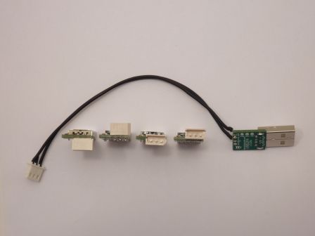
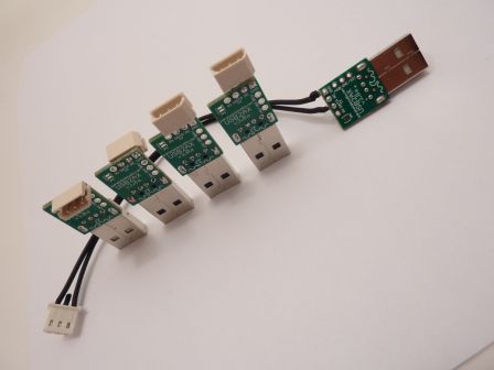
Here are the different ways of connecting the board to the Dynamixel bus that I tried:
Bent, on the bottom:
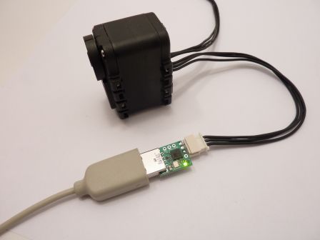
Bent, on top:
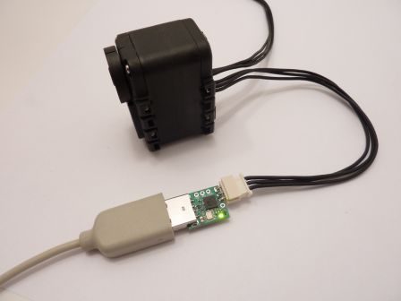
Straight, on the bottom:
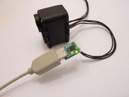
Straight, on top:
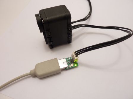
Cable (notice that only GND and DATA are connected. VBAT is not used and can be omitted):
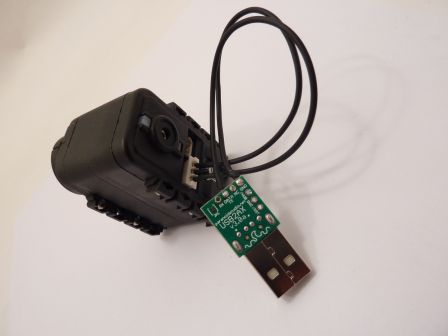
The USB receptacles of my Beagleboard-xM are stacked one over the other, like that:

In such a case, having an angled connector can be very useful.
And please imagine that I would use a real angle connector, the same used in the original USB2Dynamixel, so it's wouldn't feel as brittle as the "bent with pliers" ones I show here.
In other cases unfortunately, it's a waste of space, I agree on that.
As Tyberius reminded me, providing the USB2AX with a connector already soldered is much more sensible than to let users solder it themselves: a product ready to be used out of the box is much more likely to appeal to beginners and people who just want it to work. It will also reduce user errors and demand for support. And more experienced people who want to customize the connector still can do it, it's not closed or hidden.
Determining which type of connector to use to appeal to most users is an important question, I really have to give it more thoughts, and would welcome any argument for or against each possibility.
The firmware is open source, and can be found here: https://www.assembla.com/code/paranoidstudio/git/nodes
It's the git repository that comes with the wiki where the documentation is, and there are links in the documentation too.
iBot already proposed patches and awesome new features for alternative firmwares. I will incorporate these to the repo at after review, but it's not a necessary step: you can use and distribute your own modified versions as long as it respects the LGPL license.
Bent, on the bottom:

Bent, on top:

Straight, on the bottom:

Straight, on top:

Cable (notice that only GND and DATA are connected. VBAT is not used and can be omitted):


The USB receptacles of my Beagleboard-xM are stacked one over the other, like that:

In such a case, having an angled connector can be very useful.
And please imagine that I would use a real angle connector, the same used in the original USB2Dynamixel, so it's wouldn't feel as brittle as the "bent with pliers" ones I show here.
In other cases unfortunately, it's a waste of space, I agree on that.
As Tyberius reminded me, providing the USB2AX with a connector already soldered is much more sensible than to let users solder it themselves: a product ready to be used out of the box is much more likely to appeal to beginners and people who just want it to work. It will also reduce user errors and demand for support. And more experienced people who want to customize the connector still can do it, it's not closed or hidden.
Determining which type of connector to use to appeal to most users is an important question, I really have to give it more thoughts, and would welcome any argument for or against each possibility.
The firmware is open source, and can be found here: https://www.assembla.com/code/paranoidstudio/git/nodes
It's the git repository that comes with the wiki where the documentation is, and there are links in the documentation too.
iBot already proposed patches and awesome new features for alternative firmwares. I will incorporate these to the repo at after review, but it's not a necessary step: you can use and distribute your own modified versions as long as it respects the LGPL license.
Hi xevel
My preferred approach would be this one:

I would really recommend that you extend the board by a couple of millimetres to ensure the connector sits firmly on the surface of the PCB. In your assembly I imagine the connector is slightly raised because it colides with the Pins of the ATMEGA.
The reasons are:
1) The form factor is as compact as possible (ie the tall parts which are the USB connector and the AX connector are on the same side of the PCB)
2) The AX connector will sit firmly on the PCB. This helps with durability and reliability.
3) A user that would need an angled connector is likelly and advanced user who really knows what he's doing.
Therefore, I trust that kind of user is able to unsolder the connector (it's an easy steps - 3 pins only) and replace it with its own connector.
You could even supply the model with the vertical connector pre soldered and an extra angled connector inside the package if the customer wants to replace it. (alhtough I don't find this essential)
I also agree with Tyberious that the connector should come pre soldered.
On that end, I must also recommend that you use Heat shrink tube around the PCB to protect it from ESD and wrongful handling.
We sell HaViMo 2 which is a product that used to come in a case and now comes without a case.
You can't imagine the increase in number of RMAs we have now due to ESD and improper handling because the PCB is not protected.
Heatshrink tube is a simple, cheap and effective solution to protect the PCB. (we had a product that used this technique and it worked very efficiently)
Again, advanced users (who know what they're doing... ) can easily cut it to access the special pins you have on the side or to solder a different connector if the Heatshrink tube is interfering.
Regards
Pedro.
My preferred approach would be this one:

I would really recommend that you extend the board by a couple of millimetres to ensure the connector sits firmly on the surface of the PCB. In your assembly I imagine the connector is slightly raised because it colides with the Pins of the ATMEGA.
The reasons are:
1) The form factor is as compact as possible (ie the tall parts which are the USB connector and the AX connector are on the same side of the PCB)
2) The AX connector will sit firmly on the PCB. This helps with durability and reliability.
3) A user that would need an angled connector is likelly and advanced user who really knows what he's doing.
Therefore, I trust that kind of user is able to unsolder the connector (it's an easy steps - 3 pins only) and replace it with its own connector.
You could even supply the model with the vertical connector pre soldered and an extra angled connector inside the package if the customer wants to replace it. (alhtough I don't find this essential)
I also agree with Tyberious that the connector should come pre soldered.
On that end, I must also recommend that you use Heat shrink tube around the PCB to protect it from ESD and wrongful handling.
We sell HaViMo 2 which is a product that used to come in a case and now comes without a case.
You can't imagine the increase in number of RMAs we have now due to ESD and improper handling because the PCB is not protected.
Heatshrink tube is a simple, cheap and effective solution to protect the PCB. (we had a product that used this technique and it worked very efficiently)
Again, advanced users (who know what they're doing...
Regards
Pedro.
Pedro,
On the topic of putting the Actuated Character code into the USB2AX, this looks quite simple. I have already sent to xevel a version of the code which interprets the packets as they pass through to perform SYNC READ, and you might easily adapt that. I would expect good performance, because despite slightly higher latency, you will be running at 12M (USB2AX) instead of 115K (CM5). Maybe this would allow you to use your low cost embedded wifi unix board instead of Roboard.
I was also contemplating adding an interpolated move command into an alternative USB2AX code version. This would add number of steps and time values to the front of a SYNC_WRITE to offload this real time task to the USB2AX. There is not enough memory in USB2AX to hold pages though, so it would be move to position from last position. Not sure whether to do straight line interpolation or to control acceleration as the Robotis motion engine. Any interest ? This version would be even easier to convert to support the Actuated character.
Hi iBot
Thank you for your reply and information.
I was not personally involved in the Actuated Character project (I only know the principles behind it and the goals achieved from what Limor shared with us throughout the project). However I will let Limor know and he should follow up on this.
FYI we're also expecting to get a new team member to focus especially on development of the various robotics projects.
About your ideas to offload part of the motion control to the AX-12A it seems like a very nice idea.
Your question about using linear interpolation or some form of S curve, if I understand the implementation of S curve in Robotis (at least wehn playing motion pages) is implemented by the main controller (not controlled by the servo).
From what I understand every 8ms it sends a position set command to all servos; it is up to the main controller to decide how much each servo moves every 8ms. (moving higher distances in the middle of the motion and lower ones at the beginning and end).
If I understood your post correctly, the USB2AX can only know about the "previous" and the "next" position" (it can't hold the full motion page).
If you'd be sending it commands every 8ms, then the main controller can do the S curve at its discretion.
If you want to offload more than 8 ms of work to the controller then maybe two optional arguments that may be nice to add at the end of the MOVE command would be "time" and "acceleration", meaning this command should be performed during X ms and have this Y acceleration.
I believe the USB2AX will be able to cope with this probably since it only needs to know the target position and make some internal calculations (not sure how the algorithm would work in full - it may need some though into it) but it could be a very nice solution indeed.
Once again thank you and Regards
Pedro.
Hi!
Just tested one of the usb2ax and it worked fine. The only thing that was not immediate for me in the process was installing the driver for windows 7, but then I quickly found the .inf file over here, downloaded it, gave it to windows and all got sorted out.
I tested controlling a Dynamixel AX-12 servo from Robotis' RoboPlus Dynamixel Wizard and everything worked perfectly on the first try.
Cheers!
Marco


